Quote:
Originally Posted by dayj1

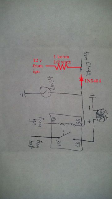
You are correct that you don't want to connect the trinary switch directly to the relay along with the PCM control for the fan. The diode is backwards in the diagram above. In addition, your PCM will eventually throw a code about the fan control circuitry because it uses the relay coil as a pull-up resistor to 12V. To defeat that check, you can add a resistor to 12V between the diode and the PCM. I updated your diagram to show what I'm talking about. Changes are in red.
 |
Ok I've been doing some thinking since it would be a royal pain to run another ign wire to my pcm based on location:
First off I think I'm going to change to pin 33 on C2 to turn on my second fan since my first fan already stays on most of the time anyways. Also, could I just wire the diode and resistor in parallel instead of adding another ign wire? If my thinking is correct, this should be the same since the pcm would always see the 12V from pin 86 on the relay passing through the 1kOhm resistor.
If I did leave the diode and resistor out all together, would it actually damage the pcm or just throw the code?