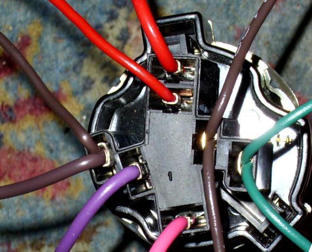
I was piggybacking on a other thread, but that became to confusing with the original question, So I have stolen a quote:
Quote:
Originally Posted by fixit-p

your connector should look like this.


Ign Switch power - Red with black pigtail coming off the side Bat
Ign Switch start - purple =Sol
Ign Switch coil - pink =Ign
Ign Switch ACC - orange =Acc
Ign Switch IGN - brown =Ign[/
The brown and green wires on the right are the G1 and G2 terminals the brown ignition wire is one on the left. |
3 questions, hopefully not to stupid..why is there nothing mentioned about a starter relais, or is that the "fusible link"? I know there is the solenoid, but isn't it safer to have a relais guide the feed there instead of thrue the ignition switch?
secondly (be gentle) ACC on my ignition switch stands for? Accesories? I see in the diagram it goes to a whole lot of things after the fuse panel, so that only has power with the ignition turned on right?
then it would make sence why there are so many wires coming from the egnition switch as shown on the picture (not the diagram)
last one for now: do I still need the voltage regulator that was mounted left fron next to the headlight?