Seems like progress is slow and there is a million little things to do. But the 'to-do' list is down from over 4 pages to about 3 1/2, so I guess that's progress.
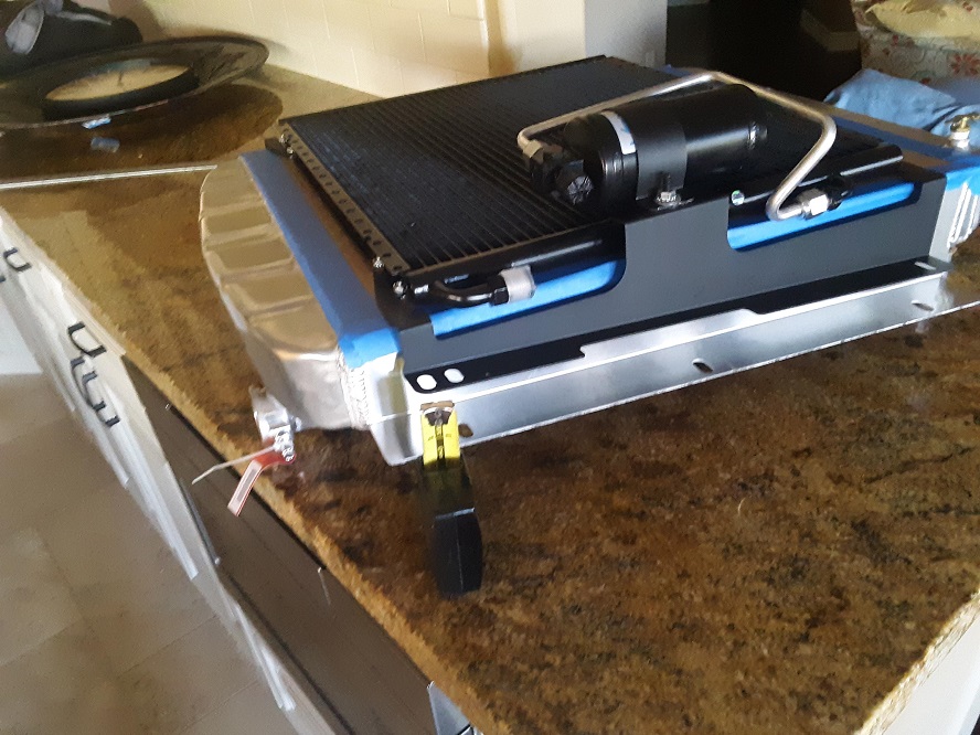
The US Radiator for my truck arrived undamaged and it looks pretty good. The bolt holes to mount it into the truck's radiator support were off by an inch and I had to redrill them, but other than that it is a nice piece.
I put the Vintage Air condenser on it to see how it was going to fit - it didn't. The brackets on the condenser are about 1 1/2" short.
I managed to get to work in the kitchen by telling my wife that the fins on the radiator and condenser were very delicate and might get damaged in the shop. That worked for about a day.
The VA part number for the condenser kit for the AD Chevy is the same as for the GMC. But the GMC has the radiator pushed forward about 1 1/2" for the longer GMC I6 engine.
I bought it from my local SoCal shop, and to their credit they went to bat for me with VA, but VA said that they'd supplied the correct part number for my GMC. They offered to send me a 'universal' bracket I could modify. SoCal said they'd refund my money if I wanted to bring it back. Looks like I'll have to fab my brackets and I'm pretty disappointed in Vintage Air's customer service.
Well onward and upward, I guess.
I needed a fan shroud and was just going to build one out of aluminum when I had this brainfart of making one with a 3D shape for a little more 'factory' look. Shaping it out of metal on the english wheel and welding it together looked pretty time consuming and frankly above my skill level so I began to think about something in fiberglass.
I've seen DIY speaker boxes made from fiberglass and an MDF form and decided I try to use that technique to make a fan shroud.
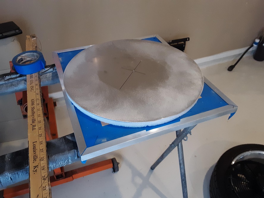
I cut a piece of 3/4" MDF the same size as the core or my radiator to use as the base for the 'plug' of my mold. I reinforced the edges with some aluminum angle. Next I went to the local craft store and bought some styrofoam to use as a spacer, then topped that with a 18" aluminum disk (that I will eventually use as the mount flange for the electric fan)
Here's the 'sandwich' of MDF, styrofoam and aluminum
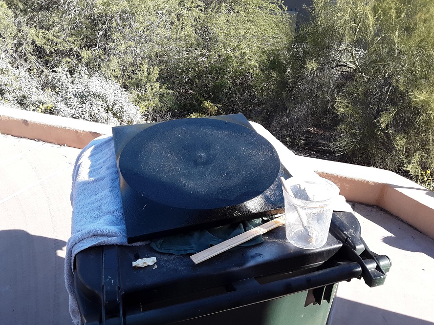
To form the shroud, I took an old cotton t shirt and stretched it over the plug. The front had too many welding burn holes and a sewn in pocket, so I used the back.
I stapled the t shirt to the MDF board and saturated it with epoxy resin to form a 3D shape
I ground the back side of the shroud down to the aluminum angle braces then I pried the MDF and styrofoam plug away from the shroud. Here's what it looks like from the back-
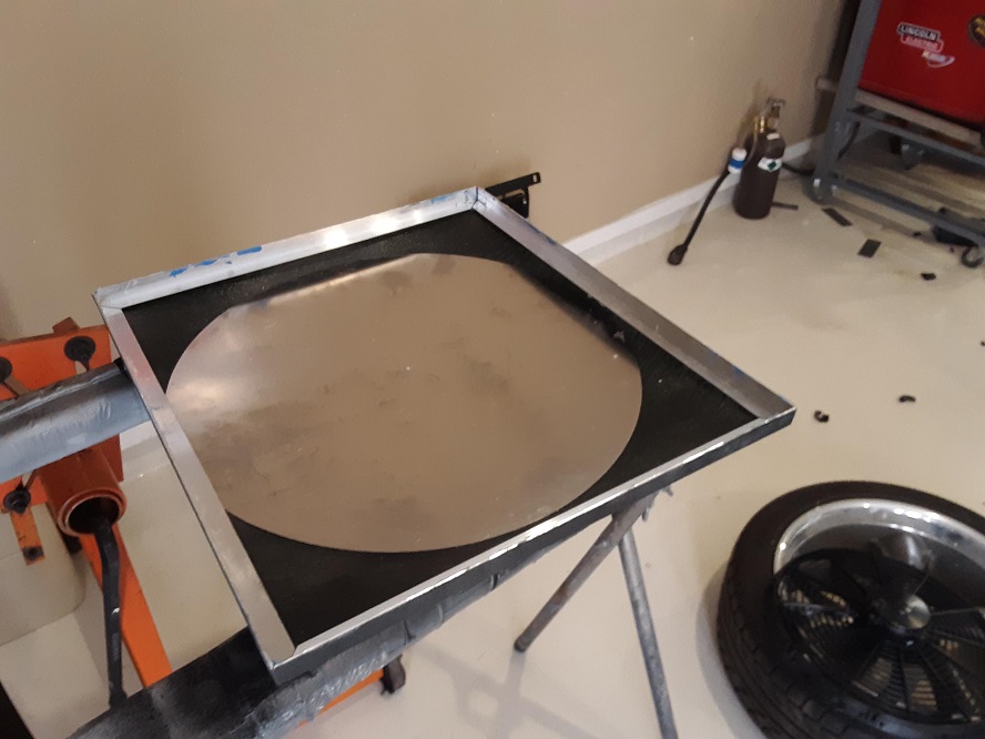
I will fiberglass the inside of the fan shroud with about three layers of 1.5 oz mat to stiffen it up for durability. I'll use a router to cut the aluminum for the fan once I get it stiffened up with mat. Here's what the whole thing will look like with a 1900 CFM Spal fan. I'd like to do something with a variable speed controller for the Spal fan. Going to look for some sort of PWM controller with a temp input.
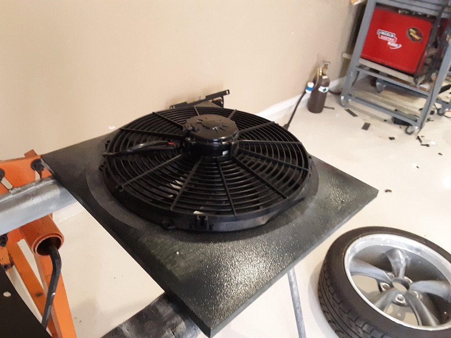
For the outside, I'll skim it with bondo then spray it with Featherfill. Top coat will be a semi-gloss black trim paint to give a 'factory' look. Note the burn hole in the tshirt.
I've never made anything out of fiberglass, so if anybody has any comments or suggestions, I'm all ears.
On to other problems.........
Almost ready to string my harness so I can shorten/lengthen wires and loom up the harness, but before I can do that, I needed to decide where the coil packd are going to be located.
The AD frame is pretty narrow and the headers run close to the frame rail, so mounting them there was out. I didn't like the idea of mounting them on the firewall or inner fenders (they are kind of ugly) and mounting them in the cab meant 8 high tension leads had to get into the engine bay, which wasn't very appealing.
Finally decided that I mount them under the engine on the front cross member. I built a steel 'shoe' to support the coils and drilled and tapped the cross member to attach it. It will be almost invisible in the engine bay.
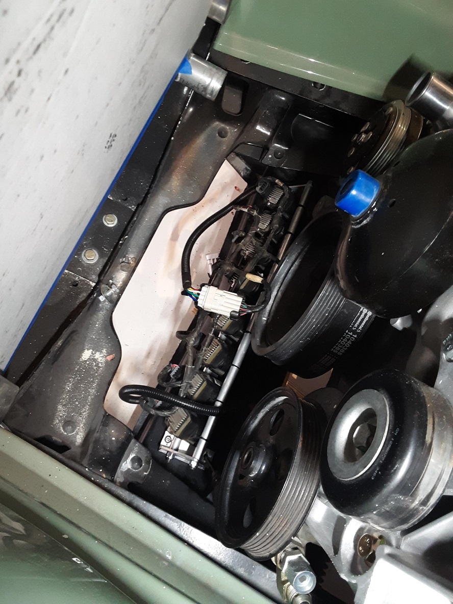
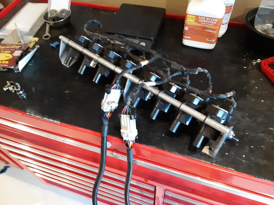
I might build a little shield/cover out of stainless for it if I get ambitious. Here's the rack of coils ready to bolt to the adapter shoe on top of the cross member-
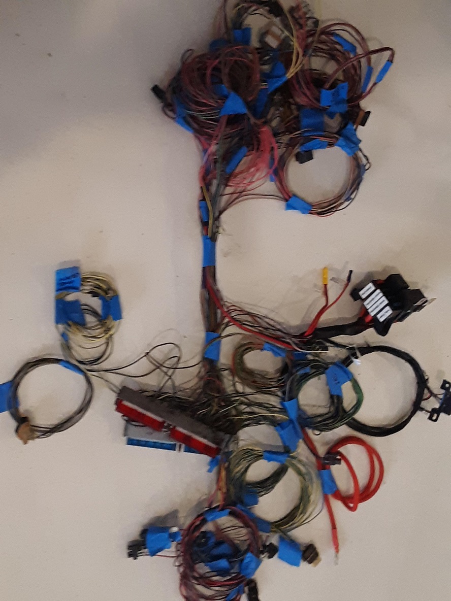
I isolated all of the sensor leads by un-pinning/re-pinning them from the PCM connectors and wrapping them individually in loops. My plan is to mount the PCM and fuse box in the cab and then run the wires to each sensor individually. This will tell me where I need to lengthen or shorten wires and how I can loom the harness to have as little as possible showing as you look into the engine bay,
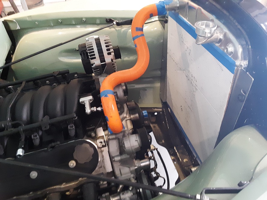
I'm going to weld up some stainless mandrel bends to use for radiator hoses and once they're welded, take them to Wyatt's shop and polish them up. I used the ICE header legos to mock up the hose before start hacking up expensive madrel bends in 304 (the legos are the wrong diameter, but this gives me the general idea)
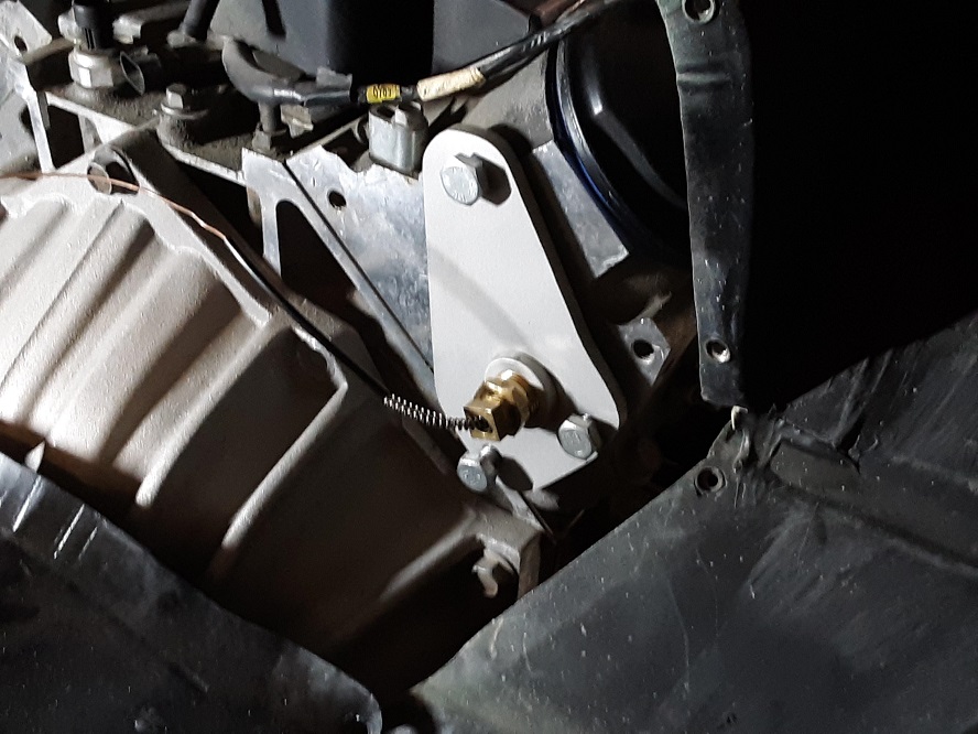
The truck was already painted with the engine in it when I decided I wanted to use original gauges, so I couldn't machine the cylinder head for the temp sensor bulb. I pried out a core plug on the back of the head and made this adapter plate to mount the temp bulb. Bonus that there is no bulb capillary tube in the engine bay to clutter it up.
Just in case you were wondering, 66F and clear last week in Phoenix. Shorts and fiip flops and working with the shop door open and heat off. Come June, I'll have to pay the piper for my weather smugness, but for now......