Thanks guys, and youve talked me into it. The ammo box stays! I will look at a secure way to store the jack and a few tools in the cab.
And thanks Rusti. I see you are from Wurzburg. My mom is from Arzberg, just down the road from you. Getting parts there must be a lot of fun.
Joedoh: If Id have known that I would have just ignored it!
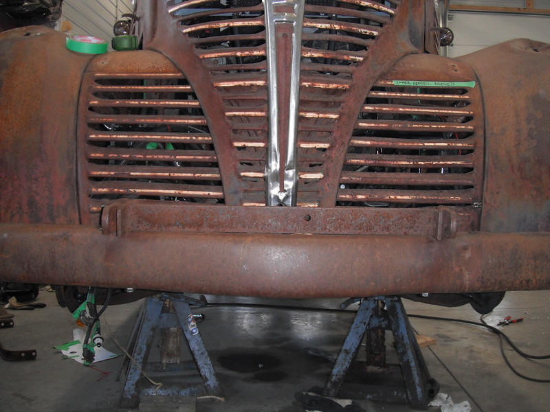
I had worked on the front bumper a short while ago, and just needed to drill holes in the shims to finish that job. I did that and then played around with them to get the best fit. I also remembered that I had a bracket that came with the truck, mounted on top of the front bumper. I dug it out and reinstalled it. I have no idea what its purpose was, but it's a million years old and came with the truck so Im keeping it attached. A side benefit is that it helps hide the fact that I had to use shims to average out the errors on the front end of this thing. Heres a couple of shots of the bumper and that bracket. If anyone knows the purpose of it, feel free to tell me:

I received a parts order from Rockauto and got to work under the hood. First was the lower rad hose. I have been using The Formula from Skymangs S10 Swap Thread, and I have the Speedway universal 19x22 rad with the outlet cut and rewelded so that it points outwards rather than inwards. As a result, I now needed a custom hose as the distances and angles were all wrong, plus the Speedway rad outlet is 1 ¾ inch rather than the 1 ½ inch that stock S10s have. I went through the various manufacturers hose charts and lost my mind trying to find something to fit. I eventually came up with a painfully easy solution. First, I bought 2 stock S10 lower rad hoses (1 ½ inch hose with one end flared for 1 ¾). I put one hose on the engine side, just like it's supposed to go, then I grabbed the 2nd hose and spun it 180 degrees so that it attaches to the 1 ¾ inch radiator outlet. Here are the 2 hoses, which actually have a straight stretch where they want to line up with each other:

Now it was just a matter of picking a spot along that straight stretch and cutting both hoses. With the addition of a 1 ½ inch hose coupler I ended up with this. Length and angles are just right:

Once installed, this is what I had. Fits like a glove:

The upper rad hose looked like it was going to be fun, as its 33 inches long and shaped like a snake. I fooled around with it for a bit, then discovered that if you loosen the clamp on the thermostat end and twist the hose clockwise, it ends up looking like this:

Now I just had to add a piece of hose with a 90 degree bend that fit the Speedway rad (1 ½ inch). A 1 ½ to 1 ⅜ coupler then joined the 2 hoses.

Im not sure that Im fully happy with it, but it will work for now. Before I get rid of my parts truck, I will scavenge the thermostat housing and perhaps fool around with fabbing a new outlet that goes straight up. This would shorten the length of the upper rad hose, and would look a lot neater. But thats a chore for next winter.
The heater hoses were wonderfully simple. One of them just needed to be shortened by an inch or so and it fit the Mopar heater perfectly. The other S10 heater hose is a larger diameter (why would you use 2 different diameters to plumb the heater?), but I was able to easily connect it by simply adding an adaptor that throttled it down to 5/8ths and then plugging the 5/8ths section into the heater. Again it fit like a glove (dumb luck).
The next item out of the Rockauto box was a wiper arm and blade. I had found plenty of wiper arms and blades on the specialty vendor sites, but then I checked the Rockauto site out of idle curiosity. Sure enough they list a wiper arm and blade for my truck. The arm is an Anco 41-01 and it is supposed to fit most vehicles in the 30s to 50s timeframe. The arm comes with adapters to fit common wiper posts (or whatever you call the spots where the arms go on). My kit had an adapter, but it was too tight to fit by about 10 thousands of an inch. My wiper posts were exactly 0.25 inch, and I didnt want to risk overdoing it by just running a ¼ inch drill bit through the adapter. To remove the small amount needed I simply rolled up some 220 grit sandpaper into a tube shape, stuck it into my drill and ran it through the adapter. It only took a minute or two, and I was able to sand away just enough that I had a nice tight fit. Here is the Custom Inner Bore Enlargement Tool (patent pending):

And here is the adapter, pressed onto the wiper post and secured with 2 tiny set screws:

The arm could now be pressed onto the wiper assembly, and it was time to tackle the next problem. Vacuum motors have a kind of silly charm to them, and I have a pair that work, however I am fully aware of their limitations. One thing I had read about before ordering the Anco conversion arms was the fact that the spring in these arms is hellishly strong. This makes for great wiper to glass contact, but it easily overpowers the ability of vacuum wipers to actually be able to move the blades back and forth.
I tested my wiper arm and I realized right away that it was way too strong for my vacuum wipers. I read a few posts where people looked for softer springs or tried different techniques to change the strength of the springs, and as I was fooling around with the unit I had a flashback to physics class and I remembered Hookes Law which states more stretch equals more force (or something like that). Deductive reasoning led me to the idea that less stretch equals less force, so I grabbed a piece of galvanized page fence wire (strong stuff) and I made a little link that would result in less stretch of the spring. Heres a shot of the Anco arm as it came:

And heres a shot with the little link installed. The difference in down-pressure of the arm is night and day, and if I need more or less force I just have to bend up a new link that's either a tad longer or shorter. It takes only seconds to do and hopefully will allow me to individually adjust each side to the strength of each sides vacuum wiper.

I wont be able to do anything further until I have the windshield glass installed and the engine running to provide vacuum, but for now it is looking promising.
I had the assistance of my son Brian (we have done a couple of builds together), so I enlisted him to help me disassemble the doors. The doors were in wonderful condition (straight and no rot whatsoever), however they did have some issues. First, I would like to show you my favourite farmer-fix of all time:

Yup, you are seeing that correctly. At some point the door latch mechanism failed, so a household door knob and latch was installed. If I didnt have to go through a safety check I would be inclined to leave it alone, as I think it's the most charming feature of the truck!
Unfortunately I do have to replace it, and thats gonna be fun. Those door latch mechanisms are only sold in pairs, they are horribly expensive, and they are currently out of stock at every vendor on earth (I checked). I may go for a set of bear claw latches which are safer and far cheaper (and are actually available). In the meantime I have tons of stuff to do. The windows in the doors had been cranked down to the fully open position, and the regulators were stuck. We managed to get the doors fully disassembled and found some pleasant surprises. First was the glass: I had budgeted for new glass as my windshield glass was yellow and delaminated. The door glass however appears to have been replaced at some point as it was in mint condition in both doors, not even scratched.
The next pleasant surprise was the regulators. A quick check showed that nothing was broken and all the gears were in alignment. The regulators had simply sat too long, and rust had built up and old grease had hardened. A thorough cleaning with hot soapy water, some wire brushing, a few spritzes of brake cleaner into some hidden crevices and some gentle back and forth turning of the cranks got things moving nicely. Once the gears were given a coat of lithium grease and the bushings were oiled, both regulators could be turned effortlessly. Before and after:


The doors were then set aside and I got to work on a tail light bracket. The Fargo came with a single taillight and licence plate bracket, so a 2nd one was needed for the passenger side. They certainly werent stingy with metal back in the 40s, as the original bracket was massive. Recreating the exact shape would be a pain as it tapers down from a thick base, however the licence plate covers most of it from view so I was able to cheat a bit. Heres the original driver side bracket for light & licence plate:

I found some heavy rod and fabbed a new bracket using the old slice & dice method. This rod was heavy enough that I was able to get reasonably close to the size of the original bracket. After bending it to shape and welding up the slices I had a reasonable facsimile of the real thing.


I then added the plate that mounts the light (no idea what the original is like so I just eyeballed the driver side and used that as a guide). I bolted the light plate to the bracket and then got fancy with my welder and grinder, turning the little nuts and bolts into fake rivets to mimic the driver side. It was of course bright and shiny (we cant have that!) so I stuck it in a plastic sandwich bag, immersed in vinegar, hydrogen peroxide and salt. Heres the old and the new:

And here they sit with the bright and shiny new taillights that just got delivered:

More to follow!