
|
Register or Log In To remove these advertisements. |
|
|
|
|||||||
 |
|
|
Thread Tools | Display Modes |
 07-13-2004, 11:02 PM
|
#1 |
|
Registered User
Join Date: Jan 2003
Location: Seattle WA
Posts: 1,466
|
Alternator wiring question
I am installing a 140 amp alternator in my 71. How do you properly run a heavier gauge charging wire from the alternator? I thought the red charging wire from the Alternator goes directly to the junction block where the batt + is connected---but it doesn't---it goes to the firewall first.
Whats the right way to do this? 
__________________
FocuzTech Performance Evergreen Protective Coatings Gatorhyde...the best kept secret in spray in bed lining & protection |

|

|
|
07-13-2004, 11:15 PM
|
#2 |
|
Registered User
Join Date: Jun 2004
Location: Gainesville, Fl
Posts: 382
|
HMM you have me stumped!! the red charging wire on my truck goes directly to the batt. OHH wait do you have a volts meter on your dash??? if so that is where teh wire goes. To run a heavier gauge wire just follow yours now and where it goes replace with atleast 12 gauge.
Good luck
__________________
Man I need another 67-72!!! 
|
|
|
|
|
07-13-2004, 11:19 PM
|
#3 | |
|
Registered User
Join Date: Jan 2003
Location: Seattle WA
Posts: 1,466
|
Quote:
Interesting---yes I have an ammeter---140 amp would need more than 12 gauge don't you think? Is the ammeter in line...I am concerned that may be a point of resistance...anyone? 
__________________
FocuzTech Performance Evergreen Protective Coatings Gatorhyde...the best kept secret in spray in bed lining & protection |
|
|
|
|
|
07-13-2004, 11:21 PM
|
#4 |
|
Registered User
Join Date: Jul 2004
Location: Braggs, okla
Posts: 161
|
here is a link, to a v-8 wiring diagram
http://www.rayschevy.com/images/guid...cylengcomp.jpg not sure if it will help, but wont hurt, and did you upgrade to an internally regulated alt
__________________
78 dualy crew cab wife calls "the beast" 79 silverado "yeller" 99 tahoe 02 Gmc sierra |
|
|
|
|
07-13-2004, 11:51 PM
|
#5 | |
|
Registered User
Join Date: Jan 2003
Location: Seattle WA
Posts: 1,466
|
Quote:
Thanks I have the diagram...but couldn't figure out where that stinkin' red wire went. Yes this alt. is internally regulated---I am a fan and owner of the 94-96 GM B-Body's--otherwise known as Caprice's and ImpalaSS's---I happen to have a Police Version and was scavaging a Taxi Cab lot and found an alternator--$25 later I have the alternator and all the parts to rebuild it---140 amp is what came in them...plus the ouput is available in a lower rpm range.
__________________
FocuzTech Performance Evergreen Protective Coatings Gatorhyde...the best kept secret in spray in bed lining & protection |
|
|
|
|
|
07-14-2004, 07:00 AM
|
#6 |
|
Senior Member
Join Date: Jul 2001
Location: Muskegon,MI,USA
Posts: 6,026
|
On stock wiring harnesses, the red wire from the alternator joins the feed wire, (the red wire that comes from the the junction on the right fender). The joint is inside the harness close to the voltage regulator location.
A 140 amp alternator will need a fair size wire to carry the current. I would go with a separate wire back to the battery, #6 or possibly larger. Jim |
|
|
|
|
07-14-2004, 07:14 AM
|
#7 |
|
blood type; Retumbo
Join Date: Jan 2004
Location: next to my reloading bench
Posts: 10,269
|
first off I have to say WOW! is that an engine or a trophy? one sweet looking engine bay.
I would go with a 6 G wire & run it to the batt stud on starter. ditch the factory amp guage. put in a voltmeter running from the ign on hot wire at switch & other end of gage to ground. that way the gage shows system voltage. solder all connections as with that level of current any resistance will create a lot of heat & possible start a fire.
__________________
Man rule #77...if you own a 67 stepside with a caddy 472 you will never be in danger of loosing you man card |
|
|
|
|
07-14-2004, 07:39 AM
|
#8 |
|
Registered User
Join Date: Feb 2002
Location: Vacaville, CA
Posts: 2,745
|
Check out the diagram on this page.
http://www.madelectrical.com/electri...evymain1.shtml
__________________
 70 C/10 Light Red 350/TH350, HEI, Duals w/40 series Flows, 91 seat, LED taillights 70 C/10 Light Red 350/TH350, HEI, Duals w/40 series Flows, 91 seat, LED taillights 99 Pontiac S/C GTP, SLP Ram Air hood, GMPP Konis & springs 95 Neon ACR, MP PCM, AFX UDP, 3.0 CAI |
|
|
|
|
07-14-2004, 10:45 AM
|
#9 |
|
Registered User
Join Date: Jan 2003
Location: Seattle WA
Posts: 1,466
|
Well guys it looks like I have some major re-wiring to do.
__________________
FocuzTech Performance Evergreen Protective Coatings Gatorhyde...the best kept secret in spray in bed lining & protection |
|
|
|
|
07-14-2004, 11:09 AM
|
#10 |
|
Registered User
Join Date: Mar 2003
Location: Bremerton, WA
Posts: 1,839
|
dang
Thought you said this was goiong to be a simple swap.....
__________________
Silence is golden, duct tape is silver. - Scott |
|
|
|
|
07-14-2004, 11:22 AM
|
#11 |
|
Registered User
Join Date: Jan 2003
Location: Seattle WA
Posts: 1,466
|
It's simple if you take the easy way...can't upgrade the alt without the wire....besides I found some nasty stuff in the wiring already this a.m.
__________________
FocuzTech Performance Evergreen Protective Coatings Gatorhyde...the best kept secret in spray in bed lining & protection |
|
|
|
|
07-14-2004, 01:31 PM
|
#12 |
|
Registered User
Join Date: May 2000
Location: Petrolia,Ontario,Canada but working in Port Huron,Mi.
Posts: 1,772
|
I just rewired my 71 to accomodate my 140 amp alt.
I replaced the orig. charge wire with a 10g wire. I rewired the whole front harness though.Took it all apart,added the 10g wire,relocated one the amp gauge wires,relocated the sense wire.About the only thing I kept were the feed wires to the lights. The factory design has the charge wire,sense wire,one of the amp meter wires joining at a crimped and soldered point in the wire harness. I did the MAD Electrical thing and relocated that factory juction to my firewall and installed a power distribution block. Here's some pic's. Here's the factory front harness.I"ve unwrapped it and you'll note on the right hand side is the orig. charge wire(red),the blue/white "sense" wire and the brown wire that goes to the warning light(my didn't have one). The rest of the wires feed the headlights and marker lights.The two wires for the amp gauge are there as well( one black,one Black/white stripe).  Here's the new charge wire.  Here I've wrapped the new charge wire, headlight wires ,and one of the amp gauge wires.This will make up my new front harness.I used proper wire wrap,not electrical tape  This pic you can see the terminal end of the 10g charge wire and one of the fused amp gauge wires(passenger fender)   This is the new power distribution block I mounted on the drivers firewall(Red arrow).The yellow arrow is the new feed to the fuse block.It has a 14g fusable link inline.  This is the 8g power wire that goes from the back of the 140V amp to the power distribution block on the firewall.A 12g fusable link protects that ciruit.  And here is how I made my connections to the power dist. block on the firewall. 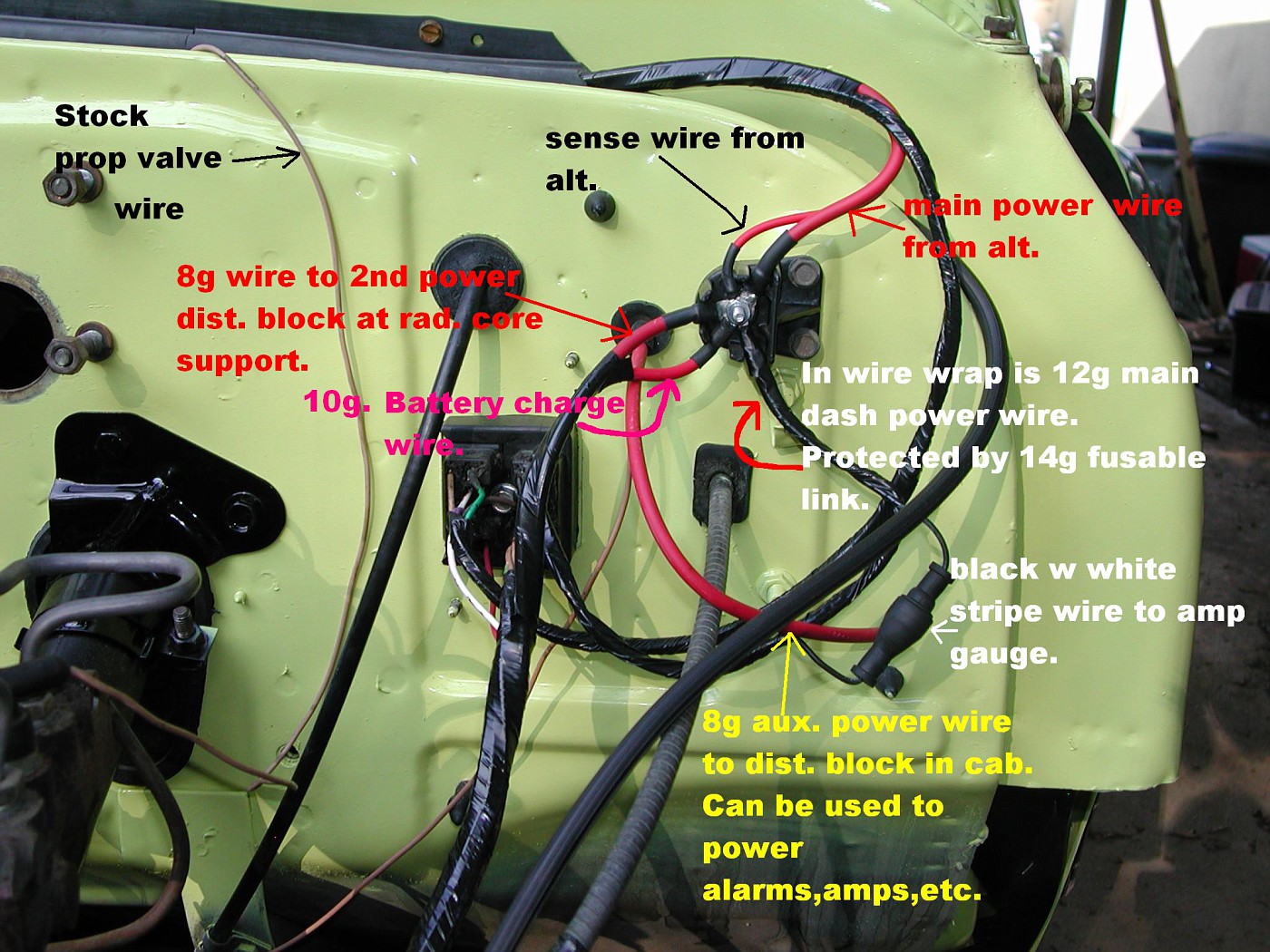 If you have any questions,just ask.
__________________
71 blazer,350SBC,approx.375HP,700R4,factory GM TPI.Dual electric fans,33x12.5x15 ATR on stock suspension. Petrolia,Ontario,Canada but working in Port Huron,MI. See ALL my Blazer pic's HERE Last edited by BobbyK; 07-14-2004 at 01:35 PM. |
|
|
|
|
07-14-2004, 02:38 PM
|
#13 |
|
Registered User
Join Date: Feb 2002
Location: Vacaville, CA
Posts: 2,745
|
If your going to do some rewiring anyway you might as well put in some relays for the headlights and electric fan if you have one. I have a CS-144 out of a 9C1, you can get a rebuild/upgrade kit for these that will put out 200amp. Also where did you get the nice alum. pulley and fan on yours just has the steel pulley and plastic fan.
__________________
70 C/10 Light Red 350/TH350, HEI, Duals w/40 series Flows, 91 seat, LED taillights 99 Pontiac S/C GTP, SLP Ram Air hood, GMPP Konis & springs 95 Neon ACR, MP PCM, AFX UDP, 3.0 CAI |
|
|
|
|
07-14-2004, 02:47 PM
|
#14 |
|
Registered User
Join Date: Jan 2003
Location: Seattle WA
Posts: 1,466
|
Bobby--thanks I really need this info---but I do have a few questions...I did find the four red wires soldered together along with the small black fuse on the drivers side core support--I understand one wire goes to the charge stud on the alt---one goes over to the old junction block, one runs down to the old external regulator plug, and one runs back up to the firewall....where does this last one go on the other side of the firewall? Whats it connected to? The brown wire coming from the firewall originally heading to the voltage regulator goes where now? Also can you tell me what wires you used on the alt regulator? There are four on the pigtail but not sure what is what. Thanks.
__________________
FocuzTech Performance Evergreen Protective Coatings Gatorhyde...the best kept secret in spray in bed lining & protection |
|
|
|
|
07-14-2004, 02:53 PM
|
#15 | |
|
Registered User
Join Date: Jan 2003
Location: Seattle WA
Posts: 1,466
|
Quote:
Headlight relays---one step at a time----  I already have two relays running my two electric fans---didn't know about the 200 amp upgrade....cool.... The aluminum fan and pulley----PAINT--as in Aluminum paint----looks good doesn't it?
__________________
FocuzTech Performance Evergreen Protective Coatings Gatorhyde...the best kept secret in spray in bed lining & protection |
|
|
|
|
|
07-14-2004, 05:35 PM
|
#16 |
|
Registered User
Join Date: May 2000
Location: Petrolia,Ontario,Canada but working in Port Huron,Mi.
Posts: 1,772
|
Mike,if your gonna go to the extent I did then just get rid of the old ext. voltage reg. wiring.
The only wires you will need are the ones comeing from the #1 and #2 terminal(white and blue wires).All the other wires going to the extenal voltage reg. can be eliminated. The red wire that goes into the plastic bulkhead connecor at the firewall feeds power to the fuse block under the dash. Now the brown wire that's in the ext. voltage wireing.You'll need to retain that as well. 1st question is do you have a full gauge dash or is it just idiot lights? I ask as the idiot light dash utilizes a bulb that is the ALT/GEN. warning light. The full gauge dash does not have that bulb,that's what the amp gauge is for. Here's how MAD says to wire it up. 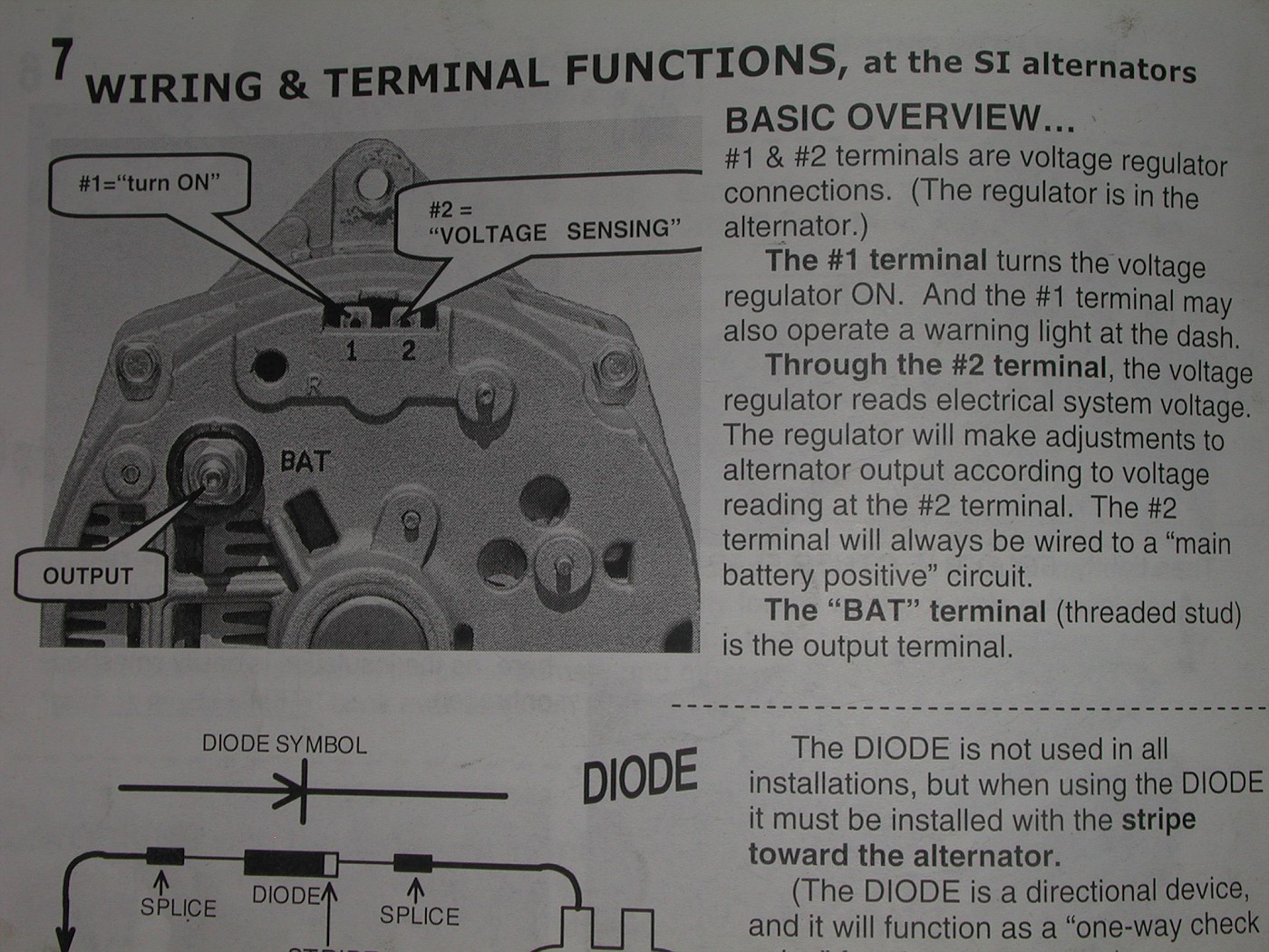 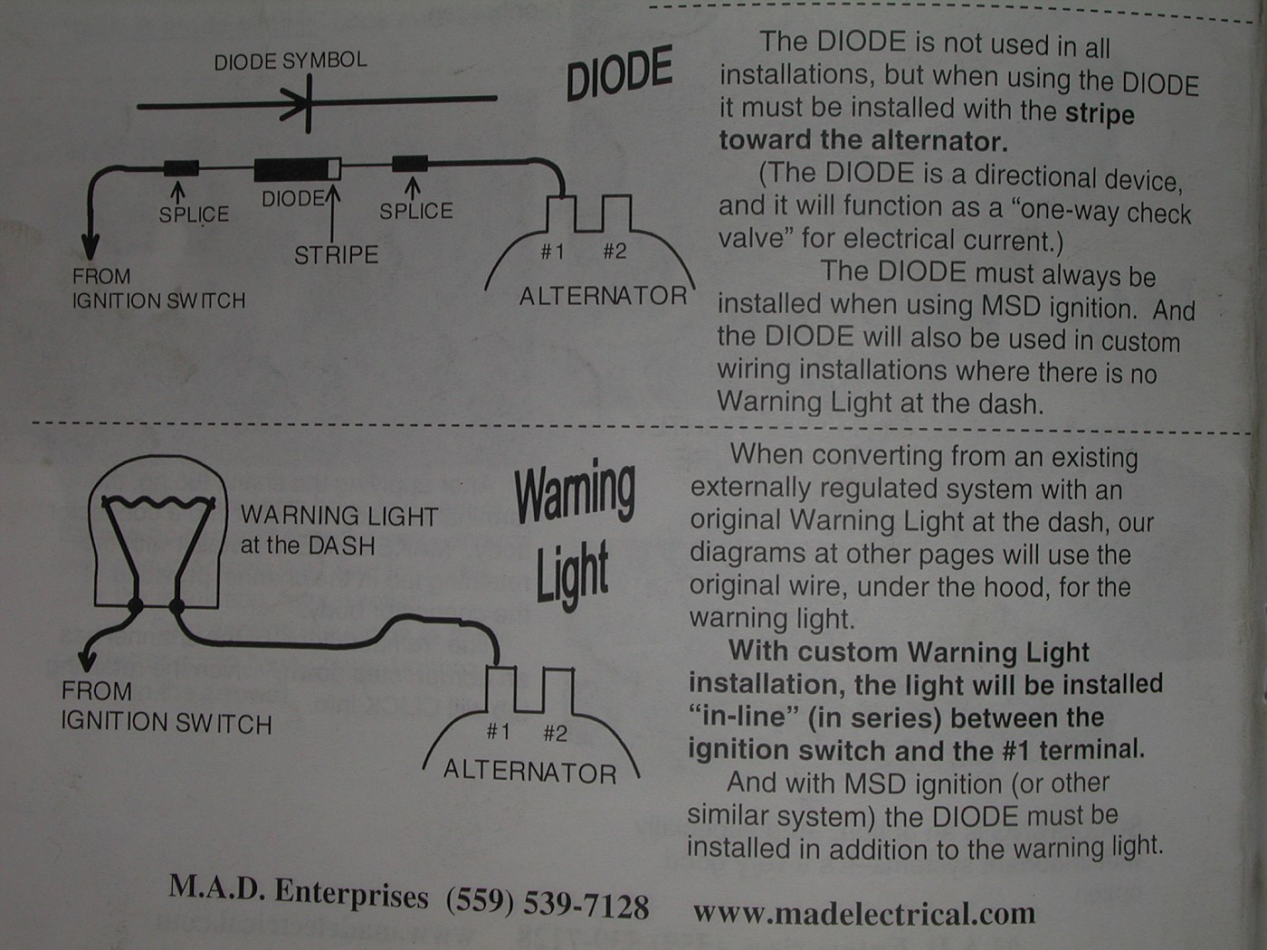   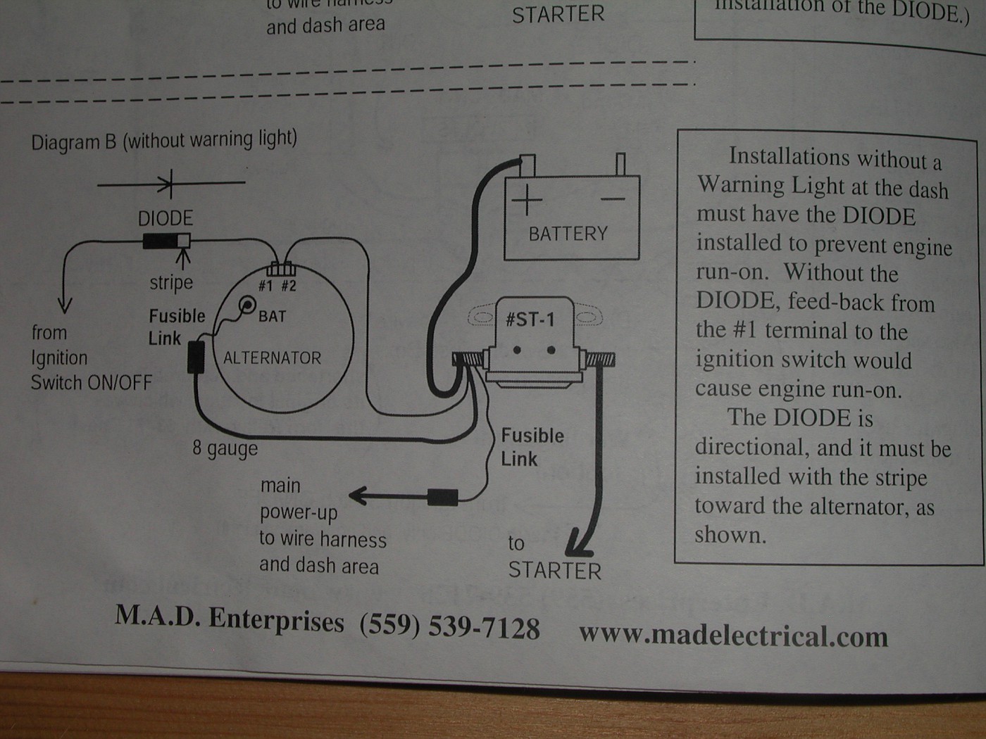
__________________
71 blazer,350SBC,approx.375HP,700R4,factory GM TPI.Dual electric fans,33x12.5x15 ATR on stock suspension. Petrolia,Ontario,Canada but working in Port Huron,MI. See ALL my Blazer pic's HERE |
|
|
|
|
07-14-2004, 06:13 PM
|
#17 |
|
Registered User
Join Date: May 2000
Location: Petrolia,Ontario,Canada but working in Port Huron,Mi.
Posts: 1,772
|
To answer your question about the 4 "CS" wires.
With a CS alt. here are the wires you use. The "S" terminal (heavier gauge red wire)-it's the "sense" terminal.It tells the alt. to bump up the output when power demand is high. You can either connect it directly to the output terminal on the alt. or,as in my case, to the power distribution block. Connecting it to the power dist. block enables the "sense" wire to actually take the reading from where all the power is being drawn from. The "L" terminal is the Brown/Red wire.This gets connected to the idiot light circiut(alt/gen. warning light). The "F" terminal is the Brown wire-It's not used. The "P" terminal is the Brown/White wire-it's not used. GM actually sells a conversion pitail.Two version though. One has a "Resistor",the other one doesn't. The "resistor" harness is used if you DO NOT have a warning light and you HAVE a gauge. You might be lucky and a local parts store may have that conversion harness as well.I think it's called an "Si" to "CS" conversion harness. The Delco part number for the resistance wire harnessis #8078. The Delco nonresistance harness is #8077 Painless Wiring has a nonresistance harness as well.#30707
__________________
71 blazer,350SBC,approx.375HP,700R4,factory GM TPI.Dual electric fans,33x12.5x15 ATR on stock suspension. Petrolia,Ontario,Canada but working in Port Huron,MI. See ALL my Blazer pic's HERE Last edited by BobbyK; 07-14-2004 at 07:19 PM. |
|
|
|
|
07-14-2004, 06:22 PM
|
#18 |
|
Registered User
Join Date: Jan 2003
Location: Seattle WA
Posts: 1,466
|
Bobby--thanks for the reply---It might have confused me a little but I think I have narrowed down all the wires. The first thing that confused me in your reply was ditching the external VR harness but retainin the blue and white wires...well the blue and white ones come only from E-VR plug...so I don't see how you can do that---however the brown wire is switched 12 volt...so I figured I would use it to feed term "L" on the alt VR plug. The other two wires on the E-VR is a large red for power (was one of four soldered together) and the brown one which seemed to have fed it 12 volts. I have since removed this entire plug assy. I think other than that I am set for now...since I am running out of time and need the truck at least running, I am going to stick with the original red charge wires that run from the alt--then "T" off---going to the original dist block by the battery and then to the fuse block under the dash...the two ammeter wires and fuses, I am leaving those there until I get bigger feed wires. Now that I read this---its sounds like a two wire...which doesn't sound right....I have the brown wire going to term "L" for turn on---I have the main feed going to the charging stud....what am I missing? Also I have gauges----
__________________
FocuzTech Performance Evergreen Protective Coatings Gatorhyde...the best kept secret in spray in bed lining & protection Last edited by miket; 07-14-2004 at 06:41 PM. |
|
|
|
|
07-14-2004, 06:31 PM
|
#19 |
|
Registered User
Join Date: Jan 2003
Location: Seattle WA
Posts: 1,466
|
I was also reading this as a guide on the wiring on the alt VR--
http://67-72chevytrucks.com/vboard/s...ght=alternator
__________________
FocuzTech Performance Evergreen Protective Coatings Gatorhyde...the best kept secret in spray in bed lining & protection |
|
|
|
|
07-14-2004, 07:09 PM
|
#20 |
|
Registered User
Join Date: May 2000
Location: Petrolia,Ontario,Canada but working in Port Huron,Mi.
Posts: 1,772
|
Sorry man,I did screw you up a bit.
Forget what I said about the Blue and White wires. If you just want to get the CS alt. running for now do this. Larger red wire-connect to the power output post on the "CS alt. Connect the brown wire from your factory harness to the "L" terminal-brown/red wire. Because you have the gauge make sure there is a 35ohm resistor installed in the brown wire circuit.That ciruit needs the 35ohm resistance to start energizing the alt.
__________________
71 blazer,350SBC,approx.375HP,700R4,factory GM TPI.Dual electric fans,33x12.5x15 ATR on stock suspension. Petrolia,Ontario,Canada but working in Port Huron,MI. See ALL my Blazer pic's HERE |
|
|
|
|
07-14-2004, 07:27 PM
|
#21 |
|
Back in the sticks
Join Date: Jan 2001
Location: Fordland, MO
Posts: 3,188
|
MikeT, I'm wanting to upgrade the electrical on my 71 as well. Which cars did you say this alternator came out of? 96-99 Impala's and Caprices? And this is the 9C1 alternator? Any idea what else it came out of?
BobbyK, thanks for helping us all out of our respective electrical nightmares. Don't suppose you have a line diagram of where all the connections are made for this upgrade do you. Minus the other stuff you have added that is. I don't have one of those battery minders like yours. I just have the old amp guage. Thanks, Jeff.
__________________
1971 Cheyenne C-10 w/700R4 and Tuned Port Injection 1969 K5 Blazer w/Tuned Port 2010 2SS/RS Flaming Orange Camaro 2011 K1500 Suburban 2014 K1500 Pickup 2008 Nissan Altima? The wifes' hoopty |
|
|
|
|
07-14-2004, 07:53 PM
|
#22 | |
|
Registered User
Join Date: Jan 2003
Location: Seattle WA
Posts: 1,466
|
Quote:
The alternator came out of a 94-96 Caprice 9C1 police car. It is a CS144 and it is 140 amp...not all 9C1's got this so you should be aware. Taxi Cab lot is probably the best place to find one---they may give it to you---parts are inexpensive to rebuild....great info is available at the link below. You can use the V belt pulley of the old alt but you must use the fan that came with the CS144---it's fits. Also when this is done I am going to draw out a little diagram and info on how to do this the simple way. http://www.extreme4wheelin.com/tech/...ators/tech.htm
__________________
FocuzTech Performance Evergreen Protective Coatings Gatorhyde...the best kept secret in spray in bed lining & protection Last edited by miket; 07-14-2004 at 07:59 PM. |
|
|
|
|
|
07-14-2004, 07:55 PM
|
#23 |
|
Registered User
Join Date: May 2000
Location: Petrolia,Ontario,Canada but working in Port Huron,Mi.
Posts: 1,772
|
I only have the factory amp gauge as well.
I do have a battery isolator,maybe that's what you see in the other pic's. In have nothing on paper,sorry. The amp gauge is hooked up the same way the factory did it,just in a different spot. The Black amp gauge wire is hooked to the old power dist. block on the passenger fender. The Black/White amp gauge wire is connected to,in my case,the new power dist. block on the drivers firewall. The factory made that connection in the wire harness where all the red wires are joined together.That would be the large soldered and crimped connection you would see if you unwrapped the harness.
__________________
71 blazer,350SBC,approx.375HP,700R4,factory GM TPI.Dual electric fans,33x12.5x15 ATR on stock suspension. Petrolia,Ontario,Canada but working in Port Huron,MI. See ALL my Blazer pic's HERE Last edited by BobbyK; 07-14-2004 at 07:58 PM. |
|
|
|
|
07-14-2004, 07:56 PM
|
#24 | |
|
Registered User
Join Date: Jan 2003
Location: Seattle WA
Posts: 1,466
|
Quote:
I thought so....By the way the link I posted mentions something about the "F" terminal having a resistor...not sure I am brave enough to try at this point. 
__________________
FocuzTech Performance Evergreen Protective Coatings Gatorhyde...the best kept secret in spray in bed lining & protection |
|
|
|
|
|
07-14-2004, 08:03 PM
|
#25 |
|
Registered User
Join Date: May 2000
Location: Petrolia,Ontario,Canada but working in Port Huron,Mi.
Posts: 1,772
|
Mike I just read that link.I'm not aware of an internal resistor.
Soldering a resistor in the "L" line is easy and proven to work.
__________________
71 blazer,350SBC,approx.375HP,700R4,factory GM TPI.Dual electric fans,33x12.5x15 ATR on stock suspension. Petrolia,Ontario,Canada but working in Port Huron,MI. See ALL my Blazer pic's HERE |
|
|
|
|
| Bookmarks |
|
|


 Linear Mode

