 |
Register or Log In To remove these advertisements. |
|
|
|
|||||||
 |
|
|
Thread Tools | Display Modes |
|
|
|
|
#1 |
|
Registered User
 Join Date: Jun 2015
Location: Portland, OR
Posts: 274
|
proper temp sensor wire routing
What is the proper routing for the green wire from the temperature sending unit to the temp gauge? Right now my wire runs parallel to the block, then at the last spark plug ducks left in between the block and the exhaust manifold and appears to keep going south, I lose track of it. Is this routing correct? It doesn't seem logical it would pass in between the block and the exhaust manifold. Maybe this is why the gauge doesn't read correctly, the wire has been compromised? The truck is a 1979 K25 with 350ci.
Last edited by K25alive; 04-10-2016 at 03:19 PM. Reason: added truck descrip |
|
|

|
|
|
#2 |
|
Registered User
Join Date: Jun 2015
Location: PA
Posts: 441
|
Re: proper temp sensor wire routing
if you ask me, it should not go between the manifold and engine. neither of my trucks had it like that when i got them but neither of them had the original engine in them either.
it looks like someone took the manifold off at some point and just slapped it back on without watching where the wire went. i would unhook the wire and try to trace where it goes. it probably goes down to the rear of the engine then back up to the harness at the firewall around the brake booster bracket somewhere. then reroute it safely away from the exhaust manifold. the sending unit or the wire itself could be melted/damaged and causing the gauge to read incorrectly |
|
|

|
|
|
#3 |
|
Senior Member
 Join Date: Oct 2014
Location: Ohio
Posts: 6,955
|
Re: proper temp sensor wire routing
Well here's mine. Pic #1, I put a heat sock on mine, there was just not way to keep it off the manifold. From there I routed along the frame & wheel well. I also put it in heat resistant tubing. Pic #2, It then goes back to the firewall and meets up with the engine harness. Pic #3, It goes left under the master power and then through the firewall right behind the fuse box and up to the cluster
|
|
|

|
|
|
#4 |
|
Registered User
Join Date: Nov 2009
Location: Sherman, ME
Posts: 2,361
|
Re: proper temp sensor wire routing
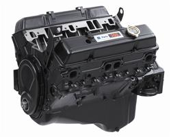
The factory valve covers had brackets spot welded to the top like on this crate engine:
 Plastic clips snapped into those brackets and held the spark plug wires along with the temp sender wire. So the original temp sender wire routing branched off from the harness at the back of the engine, ran across the top of the driver side valve cover, and then down to the sending unit. |
|
|

|
|
|
#5 | |
|
Registered User
Join Date: Mar 2011
Location: Bandera, Texas
Posts: 251
|
Re: proper temp sensor wire routing
Quote:
|
|
|
|

|
|
|
#6 |
|
Senior Member
 Join Date: Oct 2014
Location: Ohio
Posts: 6,955
|
Re: proper temp sensor wire routing
|
|
|

|
|
|
#7 |
|
Registered User
 Join Date: Jun 2015
Location: Portland, OR
Posts: 274
|
Thanks for your input everyone. I'll be sure to figure out a new route for that wire.
|
|
|

|
|
|
#8 |
|
Senior Member
 Join Date: Apr 2012
Location: Otway OH
Posts: 788
|
Re: proper temp sensor wire routing
My 75 has the wire coming over the valve cover like Ray said.
|
|
|

|
|
|
#9 |
|
Moderator
 Join Date: Oct 2008
Location: Wentworth, NH
Posts: 4,975
|
Re: proper temp sensor wire routing
I believe that's the way they were run originally.
__________________
1959 M35A2 LDT465-1D SOLD 1967 Dodge W200 B383, NP420/NP201 SOLD 1969 Dodge Polara 500 B383, A833 SOLD 1972 Ford F250 FE390, NP435/NP205 SOLD 1976 Chevy K20, 6.5L, NV4500/NP208 SOLD 1986 M1008 CUCV SOLD 2000 GMC C2500, TD6.5L, NV4500 2005 Chevy Silverado LS 2500HD 6.0L 4L80E/NP263 2009 Impala SS LS4 V8 RTFM... GM Parts Books, GM Schematics, GM service manuals, and GM training materials...
And please let us know if and how your repairs were successful. |
|
|

|
 |
| Bookmarks |
|
|