 |
Register or Log In To remove these advertisements. |
|
|
|
|||||||
 |
|
|
Thread Tools | Display Modes |
|
|
|
|
#1 |
|
Registered User
 Join Date: Dec 2012
Location: Vancouver, Washington
Posts: 1,644
|
Battery and correct wiring question
First of all, a huge thanks to everyone for patiently answering all of my recent questions.
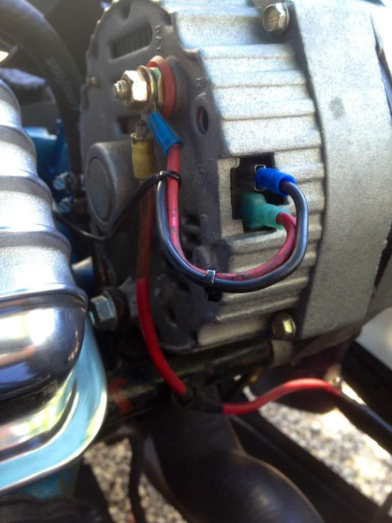
I've been plugging away at my '68 - trying to get things correct and original - and undoing some of the strange things the previous owner did. I'm getting ready to upgrade my alternator, and wanted to ask if my battery wiring is correct. First of all, the battery I have is side terminals, which I really don't care for - and the cables are fairly small gauge. I'd like to go top terminals with new cables, and wondered thoughts on what would look best in a battery. By that, a standard battery or once of the fancier ones I see in nicer vehicles at the car shows.. The way it is wired now is a positive cable going directly to the starter, and a smaller gauge wire going to a small terminal block on the passenger side fender, then a same size wire going from there to the main connector on the alternator itself. From that big terminal, a small jumper wire goes over to a spade connector on the alternator, and on the second spade connector, a small gauge wire runs to the firewall and into what I am assuming the coil. From that terminal block, a wire runs along the radiator and around to inside the cab to the fuse block. The negative cable simply goes right to the alternator mount at the water pump.  Thank you.
__________________
1968 Chevrolet C/10 LWB - 327, TH350 - 4/5 Drop |
|
|

|
|
|
#2 |
|
Msgt USAF Ret
  Join Date: Jan 2005
Location: Kalamazoo, Michigan
Posts: 8,717
|
Re: Battery and correct wiring question
The way you have it will charge the battery, but it's not the best way to do it, and if you have the gauge dash then your battery gauge may not work.
Here is the way I do it. It allows for voltage drop in the circuit away from the alternator output. The short loop wire from the no. 2 terminal is the voltage sensing wire for the regulator and all it can sense is the output of the alternator. If you wire it farther away from the alternator it will sense the voltage drop in the wiring circuit and tell the regulator to allow more output from the alternator to compensate for the lower voltage. Wiring the alternator output wire to the same junction is basically the same wiring since both wires are connected together. The difference is that the battery gauge can measure the voltage differential between the battery and the alternator because it measures each one at separate ends of the wire that connects them. This is the wire that you have that runs across the top of the radiator and is called the SHUNT wire. The other black wire you have on no 1 on the alternator is the exciter wire and it runs to the firewall block and on through to the key switch, if you have the gauge dash or it goes to the fuse block and to the dash if you have the idiot light. The fuses shown in my diagram are there to protect the battery gauge and there should be one for each wire to the gauge. They are 4 amp fuses and they are found in a small football shaped holder near the left headlight and by the junction bolt on the right fender.
__________________
VetteVet metallic green 67 stepside 74 corvette convertible 1965 Harley sportster 1995 Harley wide glide Growing old is hell, but it beats the alternative. |
|
|

|
|
|
#3 |
|
Registered User
 Join Date: Dec 2012
Location: Vancouver, Washington
Posts: 1,644
|
Re: Battery and correct wiring question
Thanks for the insight. My battery gauge is part of an aftermarket three gauge cluster mounted under the dash. I do know that there are no fuses or fusible link in any of the present wiring. I plan to diagram out what I have exactly, and if I run into any more questions do you mind if I contact you, VetteVet?
__________________
1968 Chevrolet C/10 LWB - 327, TH350 - 4/5 Drop |
|
|

|
 |
| Bookmarks |
|
|