
 |
|
|
#26 |
|
Senior Member
 Join Date: May 2007
Location: Doodah Kansas
Posts: 7,774
|
Re: Project Fargolet
outstanding!
__________________
the mass of men live lives of quiet desperation if there is a problem, I can have it. new project WAYNE http://67-72chevytrucks.com/vboard/s...d.php?t=844393 |
|
|

|
|
|
#27 |
|
Registered User
Join Date: Nov 2010
Location: calgary alberta
Posts: 8,372
|
Re: Project Fargolet
looking really good.
not to be a jerk or anything, but you mentioned you were needing to move the rear axle wheelbase ahead some. did you know the frame slides inside itself around the driver's foot area? it's welded at the factory but a lot of guys get the right wheelbase on the s10 by grinding the welds off and slipping the frame sections together or apart. I know, kinda late now. looks like to got it figured out anyway. nice work. |
|
|

|
|
|
#28 | |
|
Registered User
Join Date: May 2009
Location: Grey County Ontario
Posts: 208
|
Re: Project Fargolet
Thanks Joedoh and Tempest67. The build is slowly moving along steadily (but a bit slower right now as I have busy with the spring chores on our lot).
Quote:
With the nice weather I am finally able to work with the garage bay doors open, so I did some cleaning and grinding of the frame, and then completed the welds on the various mounts. The engine mounts however required some welding on the underside, and I had never done overhead mig welding before. Needless to say it was not pretty. After my first attempt I realized that it would be far simpler to just lift the frame onto its side and do those welds in the horizontal and vertical positions, so that’s what I did. As for that 1 ½ inch adjustment that was needed to centre the rear wheels in the rear fenders, I simply drilled another hole in each axle perch and another hole in each shock mounting plate. Here is a shot of both the perch and the shock plate with the additional holes:  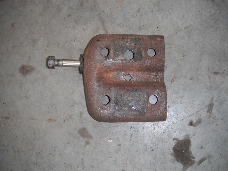 And the axle drops right into the new position, 1 ½ inches forward to give me perfect centering of the rear axle in the fenders, with just the drilling of 4 holes:  With all this done I could finally slap some tremclad paint onto the frame, just to make things clean and presentable:  I’m glad I got this done last weekend, as “the nice weather” I referred to above turned out to be a temporary thing. As I am writing this posting I am having a nice hot coffee while watching the snow falling outside. |
|
|
|

|
|
|
#29 |
|
Senior Member
 Join Date: May 2007
Location: Doodah Kansas
Posts: 7,774
|
Re: Project Fargolet
great tech!
__________________
the mass of men live lives of quiet desperation if there is a problem, I can have it. new project WAYNE http://67-72chevytrucks.com/vboard/s...d.php?t=844393 |
|
|

|
|
|
#30 |
|
Post Whore
 Join Date: Aug 2014
Location: Sacramento, CA
Posts: 10,873
|
Re: Project Fargolet
Wow, skillz to pay da billz!
|
|
|

|
|
|
#31 |
|
Registered User
Join Date: Sep 2018
Location: Ontario
Posts: 857
|
Re: Project Fargolet
that is a really good way to adjust the rear axle, and the frame looks good painted.
Thanks
__________________
https://67-72chevytrucks.com/vboard/...=797726&page=3http://https://67-72chevytrucks.com/...=797726&page=3 51 Chev 5 window on S10 with SBC 1958 Pontiac Wagon build https://67-72chevytrucks.com/vboard/...d.php?t=849781 |
|
|

|
|
|
#32 |
|
Registered User
Join Date: May 2009
Location: Grey County Ontario
Posts: 208
|
Re: Project Fargolet
In an earlier post I had shown the custom tranny mount that I had made. I had read through the “S10 swap how to” thread and saw the Skymangs method, but dealing with that weird shaped original transmission mount struck struck me as doing things the hard way, so I fabricated a simpler design:
 On the weekend I had some time and I tossed the engine/transmission back into the truck, and then started to assemble the exhaust. When I went to mount the catalytic converter, guess what was directly in the way? My new fancypants transmission crossmember! Here is the original S10 crossmember, cut to fit and welded back up, just like it was suggested in page 1 of the How-To thread. In addition to giving catalytic converter clearance, the factory crossmember has the exhaust hanger that sets the cat converter in exactly the right place, making exhaust work simpler. My engine is set at factory S10 height, so all I will have to do is find a way to shorten my exhaust system 8.5 inches to make up for the distance I moved the engine back. The entire exhaust system should (theoretically) mount exactly the same way a factory system does.  The only modification I made to Skymangs method was how I attached the cross member to the passenger frame rail. I chopped off the part of the original cross member that curves downwards and bolts to the frame rail, as it was going to make things tight between the mounting bolts and the catalytic converter. I just made a 2nd “shelf” to bolt that side of the crossmember onto. Of course the factory end that I cut off had crush sleeves to protect the tubing, so I had to do something to protect the end of the crossmember from getting squished while tightening the attachment nuts & bolts. Here is a pic of the not pretty but functional crush sleeve.  And here it sits after I slid it into the end of the crossmember and anchored it with a light weld along the edge. I know that most people would have just drilled out the mounting holes and welded in some pieces of round tube in the crossmember, but as I get further into this project I often find myself thinking “if I have done this wrong, how much work will it be to undo it?”. In this case, a quick pass of the grinder is all I need to remove that sleeve.  And here it sits in place. Moral of the story: If someone has done dozens of S10 frame swaps there is probably a good reason when they tell you to do things a certain way! 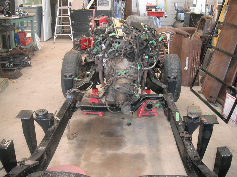 I recently had to make a decision about which rear axle to use on this build. I have a parts truck outside (4wd Blazer) but the rear axle parts on it are completely rusted up so it would need absolutely everything replaced (rotors, calipers, pads, parking brake, dust shields, lines) and this is a lot of money. My existing axle from my donour 2wd S10 is in perfect shape and needs just a brake line. It also hooks right up to the parking brake cables (so no modifying a 4wd axle to accept them) and I assume my ECU is already set up to provide an accurate speedo output based on the stock gear ratio in my existing axle. Given that this is a low-buck build, with a stock V6 that will always be driven gently, I opted to stick with the existing rear axle and just use spacers to give me bedside clearance for the wheels. Remember also that I am going for the stock Fargo look, and these spacers will put my wheels pretty much bang-on.  With this stuff all done, I sat back and had a beer. Getting the body and drivetrain to fit the frame was a fair bit of work, and there is still tons to do, but from this point on it's a bunch of mini-projects that I can putter away at as time permits. |
|
|

|
|
|
#33 |
|
Senior Member
 Join Date: May 2007
Location: Doodah Kansas
Posts: 7,774
|
Re: Project Fargolet
nice problem solving!
__________________
the mass of men live lives of quiet desperation if there is a problem, I can have it. new project WAYNE http://67-72chevytrucks.com/vboard/s...d.php?t=844393 |
|
|

|
|
|
#34 |
|
Registered User
Join Date: Sep 2018
Location: Ontario
Posts: 857
|
Re: Project Fargolet
looks great, piece by piece it is coming together
keep it going
__________________
https://67-72chevytrucks.com/vboard/...=797726&page=3http://https://67-72chevytrucks.com/...=797726&page=3 51 Chev 5 window on S10 with SBC 1958 Pontiac Wagon build https://67-72chevytrucks.com/vboard/...d.php?t=849781 |
|
|

|
|
|
#35 |
|
Registered User
Join Date: Nov 2018
Location: Ishpeming, mi
Posts: 625
|
Re: Project Fargolet
I like it. Just read through your thread. I’ll be following!
__________________
http://67-72chevytrucks.com/vboard/s...d.php?t=780018 Jason’s 56 build |
|
|

|
|
|
#36 |
|
Registered User
Join Date: May 2009
Location: Grey County Ontario
Posts: 208
|
Re: Project Fargolet
Its been about 6 weeks since I posted, so here is an update.
Next on my list was sorting out the steering column and brake pedal, but to do this I needed a seat in place so that I can test everything for access and comfort. So my dilemma was which seat to use. Here were my 2 choices:  Option A is the stock bench seat, which as you can see needs just a little bit of work (and money). Option B is the seat that came with the donour S10. This seat is comfortable and free, but it’s “period incorrect”. My goal is to drive around in a cool, reliable old truck, and I had originally wanted it to look as “period correct” as possible. This however comes with a price and adds complexity. If I am gonna go through the time and money to fix up the old seat, what about the steering column? I plan to use the existing S10 wiring harness, and the existing S10 steering column has a giant plug with a zillion wires in it which will plug right in and work (and it's free). The bad part is that it’s clearly decades newer than the original. Since I am not doing body work & paint on this truck, its no big deal to make changes later on, so I decided that for now I will use the S10 seat and column. The first thing I did was toss some plywood onto the existing Fargo seat support (or whatever you call that apron that’s welded to the floor), and then tossed the S10 bench seat on top of the plywood. I got in and sat down, and thought “geez this is comfortable”. Visually it looked a bit high, but when I checked out the dimensions of the Fargo bench seat I realized that the seat bottom is extremely tall, and is within a fraction of an inch of the S10 seat’s height. The next question was how to attach the seat. The simplest way for me was to cut a couple of 12 gauge plates to bolt to the apron, and add attachment points to give me my desired angle. Here’s how it ended up:   Each plate is bolted down in 7 spots, and then the S10 bench seat is held down by four 7/16th bolts. This is a far cry from the original bench seat which was held in place by not much at all. The original seat bottom sat on a couple of pins in the apron (not bolted down, just held there by the miracle of gravity), and the seat back was held to the cab by 4 tiny screws at the hinges. I may try to reupholster that original bench seat myself in the future, and if I do I can remove the 2 plates and pop the original seat in place within minutes. With the seat in place, I could now focus on the steering column and the brake pedal assembly. I like the bolt on design of the first generation S10 brake pedal assemblies, but after a ton of phoning wreckers and checking local yards I came up empty handed. There are zero first gens around here in the wrecking yards. This left me with either using the donour S10 assembly, or fabbing something up from scratch. I’m quicker at modifying something than I am at creating something new, so here’s what I did. First step was to cut out the old assembly, which actually was more work than I realized. The S10 dash assembly is made of layers of steel in weird shapes, all spot welded together and to the firewall. A few quick measurements revealed that I would not be able to use the combination brake pedal & steering column assembly as the column would be pointed in an inconvenient way, so I separated the column portion of the assembly and got to work on the brake pedal section of the assembly.    Here I extended the assembly downwards with a piece of plate steel (you’ll see why shortly). Like everything I did at this stage it's just tacked in place.  I spent a lot of time playing around with the brake assembly. I mean a LOT of time. The Fargo cab and front end is a tapered shape, unlike the more boxy AD truck, so clearances quickly become problems. Finding a good spot for both the pedal assembly inside the cab, and the master cylinder and booster under the hood took a lot of measuring and fiddling around. I finally found a good spot where things seem to work nicely with the exception of the brake pedal arm. The pedal arm is just a steel bar though, so I can make adjustments on its shape. I temporarily bolted the brake assembly to the firewall and got to work on the column. Did I say I spent a ton of time on the brake assembly? Well that column was far worse! First problem: That S10 seat (which is darn comfortable) puts my butt in a position where the original steering wheel is slightly offset to the right. This would drive me nuts, so a minor shift of the column to the left would be needed. Of course the dash is stamped in a shape that makes using the factory mounting holes a little challenging. So out came the original dash brace (which was both bolted AND brazed into position!) and a new brace had to be made to stiffen the dash and support the column. The Fargo dash also has tapered shapes, it rises up in the middle top and it comes out (towards the bench seat) in the middle face. There isn’t a 90 degree angle to be found anywhere, so the first brace I made was pure misery to do. I spotted some problems with the first brace, and spent an entire day on an improved version (2.0), and at the end of a long day I had it in place and was pleased with how things should bolt up. While playing around with it, I noticed that it was less rigid than I thought it would be, and on closer inspection I realized that I had grabbed the wrong sheet of metal that morning and had done the whole thing using the wrong gauge of steel. I was a bit dejected for a moment, but it occurred to me that 90% of the day had been spent measuring, trimming, figuring angles etc., so cutting fresh pieces wouldn’t be that big a deal (I now had a bunch of rather nice templates to simply trace out onto the heavier plate and cut out). Thank god I only tacked stuff together. The next day I got to work on version 3.0 and after a couple of hours it was installed in the dash. Version 3.0 was way too big, but I did this on purpose as its easier to cut it down than to make it bigger, and figuring out the additional gussets and bracing to tie the column brace to the brake assembly is easier to do in place. The length of the S10 column turned out to be rather inconvenient for a Fargo. The end of the column sits inside the cab, and the factory u-joint cannot be reused as the bend angle exceeds its limits. The best orientation for the S10 column turned out to be the same orientation as the original Fargo column (with just a slight shift to the left to line it up nice with the driver seating position). This also provided me with a nice, straight run from the base of the column to the steering box, with only one minor obstruction (the power steering pump low pressure steel fitting). Actually there was one other obstruction: the engine oil cooler lines. This however proved to be an easy fix, as I followed Joedoh’s instructions in his “Bickle” build and got rid of the entire assembly. It took me 30 or 40 minutes to get rid of the entire assembly, and this freed up some valuable space:  Here’s how I tackled the column in the Fargo: First thing was to make a template of a u-joint to allow me to make precise measurements. I attached the wooden u-joint (shaped at the 22 degree angle that the real one will sit at), and bolted to the bottom of the column. Then I hung the column onto column support 3.0 and adjusted it until I got the best fit. It was still inconvenient as the end of the u-joint was right at the firewall, but I had a solution in mind for this (more on this later). I had to bolt column support version 3.0 to the existing holes in the lower dash edge, and the bolt heads looked ugly and didn’t line up nicely with the column (due to the slight offset to the left that I wanted), so I made a plate with hidden studs so that bolt heads don’t show. I also extended the plate so that it hides the fact that I have offset the column to the left. With the column hung on support 3.0 I could sort out the lower support. I had to remove the factory S10 lower support that’s welded to the tube as it interfered with the brake pedal. Here is the column during this mock-up. The sturdy section of plate that I had earlier added to the bottom of the brake pedal assembly was meant to provide a secure attachment point for the lower column:  After this mock-up I did a final test (I sat behind the wheel and checked comfort, alignment, fit, etc) and then cut and tacked the lower support pieces, and trimmed unnecessary sections of 3.0 away (thereby creating version 4.0). Final welding and some more gussets will be added later, but this got me to the point where I could continue other work that required final placement of the column & brake assemblies. Here they sit:   I did some test wiggling, and then some test heaving and was very pleased with the results. The brake and steering assemblies are solid as a rock. The dash, firewall, steering column and brake pedal assembly are all bolted to each other in a triangulated fashion with heavy steel plate & brackets, and the Samsonite Gorilla couldn’t budge this thing (I may have dated myself a bit with that reference!). I’m hoping that 4.0 will be the final version, as I don’t want to end up at version 6.3 (unlike somebody on this board who shall remain nameless, but whose current build name rhymes with “pickle”!!!). Next I had to deal with the brake pedal. It was a little too far out from the firewall, and of course it hit the steering column part way through its range of travel and its overall shape was just not right. The pedal arm is just a nice thick steel bar so I figured I would persuade it into shape with a torch, a vice, a hydraulic press and a BFH. I worked away at it for a while, but my torch set is one of those mini-portable jobs that takes a long time to heat up a thick bar, and of course it empties out awful quick. I realized that this was not going to work so I went to my fallback plan: the old “slice & dice”. Using a thin cutting wheel on the 4 ½ inch grinder, along with my bench vice and the aforementioned BFH I managed to get it into a shape that curves around the steering column and sits at a safe and comfortable height. I still need to do some welding and grinding, after which I will post a pic. One thing that went well was the gas pedal. I had a box of leftover parts from my last build in which I used Blazer parts for my 56 Chevy wagon, and it turned out to be wonderfully simple to use one of those assemblies. I simply added a flat plate to the underside of the factory plate (which is shaped like an amoeba!) and did some fine tuning of the pedal arm shape.  Due to the shape of the Fargo cab, this assembly will bolt directly to the inside face of the firewall, without the need for a specially shaped mount (I think!). After having done the steering and brake assembly swap, I have to say that it was the most difficult work on this project so far. Unfortunately there is still lots to do under that dash, so I see a lot of upside down squirming around in that cab in my future. More to come! |
|
|

|
|
|
#37 |
|
Registered User
Join Date: Sep 2018
Location: Ontario
Posts: 857
|
Re: Project Fargolet
looks great.
be sure that your gas pedal has full travel to the floor, I needed to make a small riser for the pedal. (for a 51 Chev floor) keep up the good work, and enjoy the process., and thanks for sharing
__________________
https://67-72chevytrucks.com/vboard/...=797726&page=3http://https://67-72chevytrucks.com/...=797726&page=3 51 Chev 5 window on S10 with SBC 1958 Pontiac Wagon build https://67-72chevytrucks.com/vboard/...d.php?t=849781 |
|
|

|
|
|
#38 |
|
Senior Member
 Join Date: May 2007
Location: Doodah Kansas
Posts: 7,774
|
Re: Project Fargolet
you are a problem solver, I like the way you think. if we lived closer to each other we would hang out for sure!

__________________
the mass of men live lives of quiet desperation if there is a problem, I can have it. new project WAYNE http://67-72chevytrucks.com/vboard/s...d.php?t=844393 |
|
|

|
|
|
#39 |
|
Registered User
Join Date: May 2009
Location: Grey County Ontario
Posts: 208
|
Re: Project Fargolet
Tempest67:
Its all good! That Blazer pedal assembly was perfect for the shape of the Fargo floor and firewall. Getting it adjusted to obtain full throttle was just a matter of a couple of quick slices with a cutoff wheel, bending the rods a bit and then welding up the slices. Joedoh: Thanks! Hanging out would be a blast, after all it’s only a 19 hour drive to your place (one way! yikes!). On 2nd thought, hanging out with you is likely a very bad idea, as I would undoubtedly return home with another old truck to delight my wife. With that steering and brake assembly cut and fitted to its final shape it was time to pull the cab off (removing the cab means far easier access for a lot of stuff). The first thing I tackled was the exhaust. My S10 muffler was shot, but the rest of the system was in good shape. When I was placing my last parts order I noticed that a Walker muffler model 18112 was about 10 inches shorter than my old muffler. Since I had shifted the drivetrain back 8 ½ inches I figured a shorter muffler might make things a little easier to fit in place. I spent about 3 hours separating the various pipes and cleaning the flange surfaces and then I started to assemble the system. Imagine my surprise when the new muffler fit without any modifications to the pipes at all. No bending, no cutting, no welding. Nothing. Pure 100% dumb luck, but I’ll take it! Cautionary Note: I don’t know what this muffler sounds like, but it was advertised as a universal stock replacement type. I’m gonna detail how easy it was to do this basically stock system with a typical drivetrain shift to the rear, as it’s not Fargo specific and it applies to any S10 swap. While the pipes/muffler/cat/Y-pipe all fit together perfectly, the support hangers between the muffler and the Y-pipe were no longer in the right spots due to me sliding the drivetrain back. The hanger at the inlet to the muffler just needed to be slid back on the frame and 2 holes had to be drilled to mount it. Since the frame rises there I had to take about an inch out of the height of the hanger: 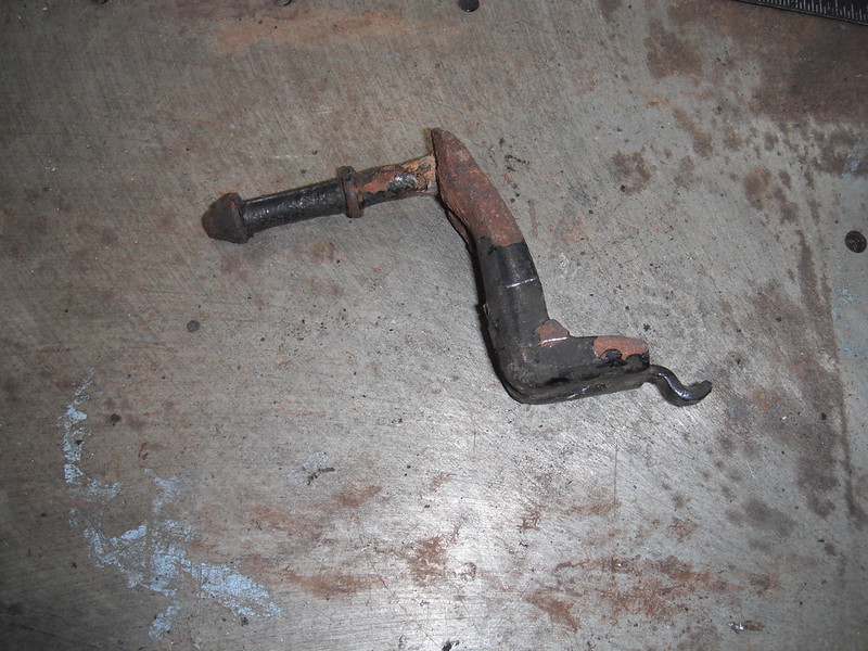  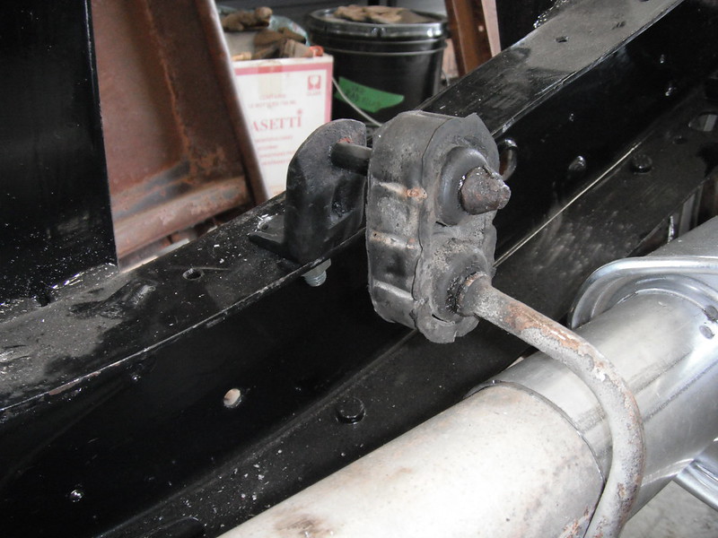 The hanger at the rear of the catalytic converter looked like it would be a little trickier, but in the end all I had to do was extend its length and weld a nut into the frame to mount it. There is a factory hole that lines up nicely to catch the little hook on the hangers, so only one hole had to be drilled to mount this one:   The original muffler had a hanger with 2 of those heavy rubber loops, likely due to its size (the original was massive), and the rubber loops were fastened to the muffler by a steel band. The new muffler is tiny in comparison, but to use the same steel band it was just a matter of shortening the band, recurving it and then bending fresh ends:  There is one more hanger that needs modification (at the front of the cat), but this will be far easier to do when I have the truck up on the hoist so I will show this later on. While the system was apart, I took the time to break free the downstream O2 sensor in the catalytic converter as it had thrown a code prior to disassembly, and there was no easier time to get it loose than now. With the exhaust sorted out, I set the various components aside as it will be easier to do stuff like brake and fuel system with more access room. More to come! |
|
|

|
|
|
#40 |
|
Registered User
Join Date: May 2009
Location: Grey County Ontario
Posts: 208
|
Re: Project Fargolet
With the exhaust sorted out, I switched over to the other side of the frame and reinstalled the fuel tank and evap canister. The fuel lines were in good shape except for one spot a few inches long where they had been retained by a plastic clip that clearly allowed water to collect:
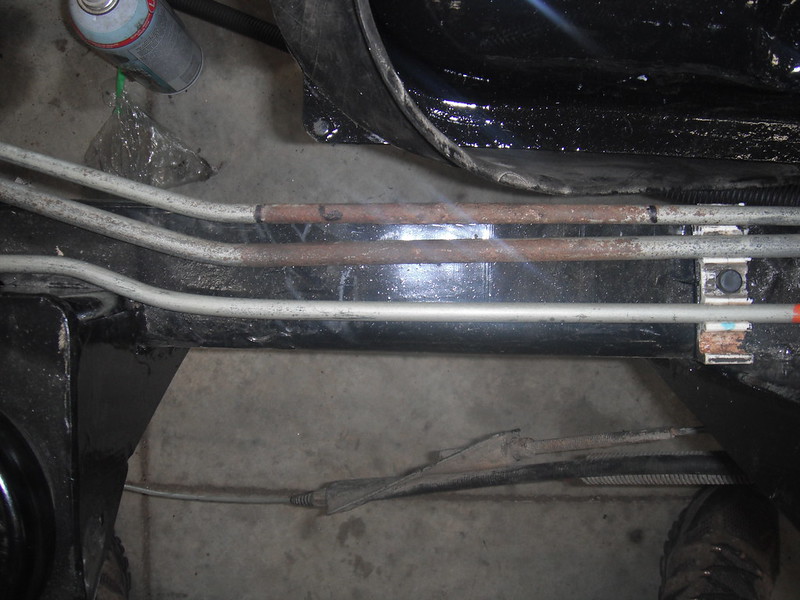 I needed to shorten the lines by 8 ½ inches due to my drivetrain setback, so the rusty area was the natural spot to do the shortening. I started by laying each fuel line on a table and tracking the outline, as well as marking the top of the fuel line so that I could rejoin it perfectly after removing the bad spot:  The bad area was removed, along with enough good material so that I lost 8 ½ inches: 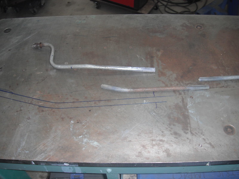 The 2 remaining pieces were joined with a compression fitting, being careful to line up the sharpie marks that I had added earlier (I snapped this shot before doing the final alignment):  And then the sharpie outline on the tabletop was used to bend the line back into the factory shape (shot taken just prior to bending line to conform to sharpie outline)  The size of the compression fittings (and the need to be able to get wrenches on them if needed) meant that I had to space the lines a little further apart, but there’s all the room in the world along those sections of frame, so I used rubber lined fuel clips to secure the lines:  The factory lines had been secured against the inner frame rail just ahead of the fuel filter by this plastic clip:  Moving everything back 8 ½ inches put this clip where the frame had narrowed a bit (and the result was the clip pushing the lines out of place). By spinning the clip around 180 degrees and by sliding it forward an inch, it now held the lines in exactly the right spot and I could secure it with a bolt to the tranny crossmember shelf that I had welded to the frame. The fit was perfect in every dimension and once again it was due to pure 100% dumb luck.  With the fuel system done I could deal with the rear brake lines. I installed the main line that runs from the ABS to the rear flex hose (ABS will most likely be deleted so the front of that line is not yet hooked up to anything). I added a new rear flex hose and new rear brake lines. I had forgotten what a treat it is to use that nickel-copper stuff. I then tossed the rear shocks back on. The front brake lines and the ABS delete can wait till the truck is on the hoist to save me a lot of crawling around. All in all, moving the stock S10 drivetrain back while retaining all the stock S10 fuel and exhaust components proved to be easy and required very few parts. I believe that its now time to seriously hit that cab as there is a ton of stuff to do there. More to come! |
|
|

|
|
|
#41 |
|
Senior Member
 Join Date: May 2007
Location: Doodah Kansas
Posts: 7,774
|
Re: Project Fargolet
beautiful work, great how to!
__________________
the mass of men live lives of quiet desperation if there is a problem, I can have it. new project WAYNE http://67-72chevytrucks.com/vboard/s...d.php?t=844393 |
|
|

|
|
|
#42 |
|
Senior Member
 Join Date: Mar 2011
Location: West Plains, Missouri
Posts: 7,559
|
Re: Project Fargolet
Nice job on detail of repairs, and changes...Jim
__________________
my build thread: http://67-72chevytrucks.com/vboard/s...d.php?t=459839 Jimbo's long bed step build:http://67-72chevytrucks.com/vboard/s...t=464626<br /> |
|
|

|
|
|
#43 |
|
Registered User
Join Date: May 2009
Location: Grey County Ontario
Posts: 208
|
Re: Project Fargolet
Thanks guys. I often get stuck trying to figure out the little things, so I’m doing my best to document generic S10 swap details that I have had to sort out. Speaking of which, here’s more!
I got started on that cab by first stripping everything out of it and placing it on blocks to lift it up. The entire Fargo floor from the seat forwards can be removed, so I am able to step inside the cab and work on things while comfortably standing on my shop floor (instead of crouching inside the cab with screaming knees).  The toeboard was badly dented and had all kinds of cutouts that are not needed, so I used it as a template to cut out a new one. I may fab up some stiffening beads to weld to the underside, but I used 13 gauge steel and once bolted down this thing has almost zero flex (I also painted it black while it was easy to do, so pic quality is not great):  The firewall also had a ton of cutouts and holes of all shapes and sizes that needed to be closed up. I figured “a couple of hours should do this”, until I counted up all the openings that needed to be shut (60 of ‘em!). 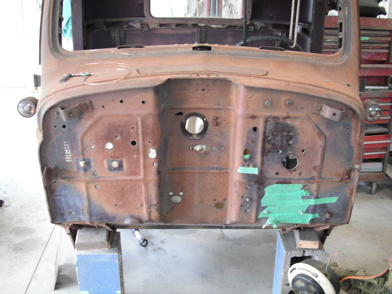  Full welds were added to previously tacked together parts::  After doing the final welds on the column support and brake assemblies, I tossed them both back into the cab to figure out the firewall passthrough. The U-joint at the base of the column ends up where I knew it would (right in the firewall) so I needed a passthrough and a sealing system.   As for the passthrough, I grabbed some steel and fabbed a box that would extend the firewall forward enough to enclose the u-joint. Unfortunately this spot is where the firewall bends down under the floor so it took a lot of fooling around to be able to match all the little bends and jogs that go on down there (there are overlapping panels as well, so this tiny little box was a bit of a nightmare to fab up!). I was going to weld the little box in place, but since I am doing this with the cab off the frame I figured it would be best to bolt it on in case I discover a clearance problem when I reassemble the truck. Here’s where I ended up (it’s temporarily fastened with just a couple of bolts)   To handle the seal on the engine side of the firewall, I just used the original ‘96 S10 rubber seal and the original bearing as it fits a ¾ DD shaft. Here are those parts on my new DD shaft, and then temporarily installed:   For the inside cab seal, I went to my parts truck (a 2000 or so Blazer) and found that it had a nice rubber flex cone to seal the column. To use this cone I had to remove the 1996 S10 lower column seal and insert the 2000 Blazer lower column seal. They both fit, but there is a clocking difference that required me to use the Blazer lower column seal to properly align the rubber boot:  I may fab up a big ring that will bolt the edges of the boot firmly down, but I have some more mods to do in that area that require pulling out the brake assembly first, so it will have to wait. I was a little tired of crouching around and working on that passthrough so I switched to something quick & easy (or so I thought). Sometimes it’s the little things that slow me right down. I found a couple of snapped screws on the glovebox door where the swingarm attaches and I figured “this should be quick”. Famous last words. I have no idea why this happens, but every so often I come across snapped off screws that resist all attempts to drill them out. I also had just run out of acetylene, so no help there. I went through 7 or 8 new drill bits, and both screws just wore the bits out. Here is one of the little buggers (it's the one on the left), and you can see the snapped off portion down inside. The construction of the glovebox door is strange, as the outer screw holes have an air gap between the glovebox doorskin and whatever the screws thread into:  I got around the problem by grabbing a carbide bit with a rounded end and I hogged out a hole that was wide enough and deep enough to lay a nut in This shot is actually the right side of that glovebox door but it’s the same process):  The nut was then welded in place and the welds cleaned up a bit. Not the prettiest, but it's for the inside of a glovebox.   And after all that I was able to reattach that glovebox door with new screws on both ends:  I repaired a couple of rusty cracks that I found on the floor near the kick panels, and then I welded in a patch to close up the big oval hole where the original gas filler tube passes through the cab floor on its way to the original gas tank (boring stuff so no pics taken). More to come! |
|
|

|
|
|
#44 |
|
Registered User
Join Date: Nov 2018
Location: Ishpeming, mi
Posts: 625
|
Re: Project Fargolet
Looking good. Nice fab work!
__________________
http://67-72chevytrucks.com/vboard/s...d.php?t=780018 Jason’s 56 build |
|
|

|
|
|
#45 |
|
Senior Member
 Join Date: May 2007
Location: Doodah Kansas
Posts: 7,774
|
Re: Project Fargolet
wow perfect planning and execution, great visualization!
__________________
the mass of men live lives of quiet desperation if there is a problem, I can have it. new project WAYNE http://67-72chevytrucks.com/vboard/s...d.php?t=844393 |
|
|

|
|
|
#47 |
|
Registered User
Join Date: May 2009
Location: Grey County Ontario
Posts: 208
|
Re: Project Fargolet
Thanks for the kind words!
The cab work continues……… I made some progress with the ventilation system, but am waiting on parts now. I also temporarily installed the parking brake pedal and release bracket, but I need the cab back on the frame before I finalize things, so no pics right now. I did however make some good progress on wipers and windshield as follows: When I stripped down the Fargo I discovered that it uses a separate vacuum wiper motor for driver and passenger sides. I also discovered that mine were completely seized. A little while ago I was doing some random internet surfing when I came across an ancient Ford service bulletin about Trico Vacuum wipers. It recommended using brake fluid, especially on old units that have sat for years. I managed to get a few capfulls of fluid into each motor, and then let them sit in different positions to let the fluid get everywhere. Much to my surprise, both motors freed up. I worked them back and forth for a few minutes and then hooked up a piece of vacuum hose to each one and provided some vacuum (by mouth) and sure enough they sprang to life! My donour S10 had a vacuum reservoir, so for now I think I will give it a whirl to see how these things do. I can always buy some electric motors and fab up a system if the vacuum units are awful (quite likely!), but these things will bolt right back in (and they are free) so for now I will see if they do the trick. My previous truck (‘56 Chevy 3200) had vacuum wipers which were not great, but the Fargo has a separate vacuum motor for each window, and the wiper blades are quite small, so I have my fingers crossed that they will work!  Next came the windshield, and as you can see, it's just a top half that slides together with a bottom half, sandwiching the glass in between. No problem, its just a matter of removing 5 screws and pulling the 2 halves apart. “How long could that take?” I asked myself. The correct answer is 6 hours.  To get it to the point in the picture above, I made use of the following: Knives & scrapers Gasolene Clamps A big wooden wedge Hammer Oxy-acetylene torch Screwdrivers Dremel Profanity Centrepunch Drill & various bits 10-32 tap Air grinder & wire wheel I truly did not want to wreck this thing so I had to be careful, but everything was so seized together that in the end some serious persuasion was required (as is evidenced by the implements of destruction listed above). These windshield frames are now made new in the States, but would be about $1700 by time I got my hands on it up here. By being very careful with when & how I heated and whalloped the pieces, I got it apart without damage and repaired the snapped screws. Now its just a matter of getting some flat glass cut and ordering the seal (the tape in the pics is holding all that cracked glass together long enough for it to be used as a template). More to follow! |
|
|

|
|
|
#48 |
|
Registered User
Join Date: Jan 2012
Location: Motown
Posts: 7,680
|
Re: Project Fargolet
very cool build

__________________
cool, an ogre smiley  Ogre's 58 Truk build Ogre's 58 Truk buildhow to put your truck year and build thread into your signature shop air compressor timer |
|
|

|
|
|
#49 | |
|
Senior Member
 Join Date: May 2007
Location: Doodah Kansas
Posts: 7,774
|
Re: Project Fargolet
great perseverance! those multi piece windshields are a pain in the behind. the 41-46 chevy windshields come apart like that only side to side, on one truck I bought a new windshield for 7 or 8 hundred, on the next I thought I would save some money and rebuilt the original, only took a month and 5 hundred.
 Quote:
next time double the profanity or at least increase the volume if you cant increase the frequency.  
__________________
the mass of men live lives of quiet desperation if there is a problem, I can have it. new project WAYNE http://67-72chevytrucks.com/vboard/s...d.php?t=844393 |
|
|
|

|
|
|
#50 |
|
Registered User
Join Date: Oct 2015
Location: PNW
Posts: 3,639
|
Re: Project Fargolet
This looks like Medusa in the morning.
 You know you're doing a in-depth build when you say something along the lines of "I'm onto the easy part" and then post a picture like that, haha. I'm very intrigued with this build. One of my favorite aspects about it is that you are using what you have. That will be the quickest way to get it on the road and enjoy it. From there, and how you feel while you're driving it, you can make changes if you want. If you decide that you want the interior to be more stock like, or more custom, you can head that direction. Meanwhile, you're running and driving with parts that are already paid for. Well done, I'm having fun watching. |
|
|

|
 |
| Bookmarks |
| Thread Tools | |
| Display Modes | |
|
|