 03-03-2013, 05:23 PM
|
#1
|
|
Registered User
Join Date: Jan 2013
Location: Leonardtown, MD
Posts: 1,648
|
Studebaker dash panels
This is the continuation of a job from last summer. To start, let's catch up...
Quote:
A few weeks ago one of the local Studebaker owners needed some panels made for the dash of his truck (1947 M5), he's revamping the dash gauge/radio arrangement and needed some fresh metal to work with. Here's the existing:
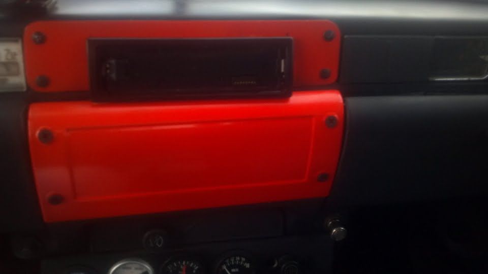
Where the factory panel has a recess, and since he has plans for installing a couple gauges in that panel, the new will be made without the recess. The flat panel above for the DIN radio will be replaced as well, with the sides tipped for uniformity.
The old panel has seen some previous holes, for whatever reason.
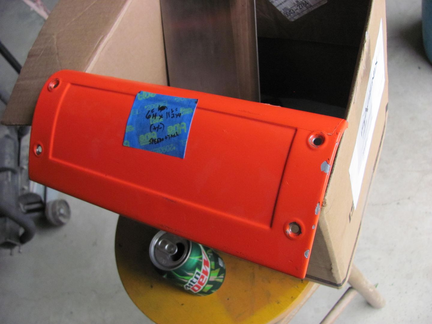
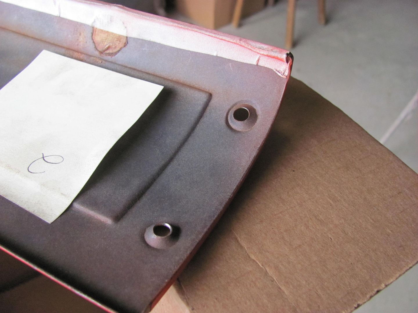
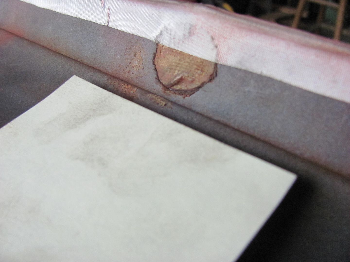
Where the rubber tire on top of the e-wheel does a nice job of forming a radius across a panel, the upper portion of the panel was a bit tighter than the 3" radius anvil will provide.
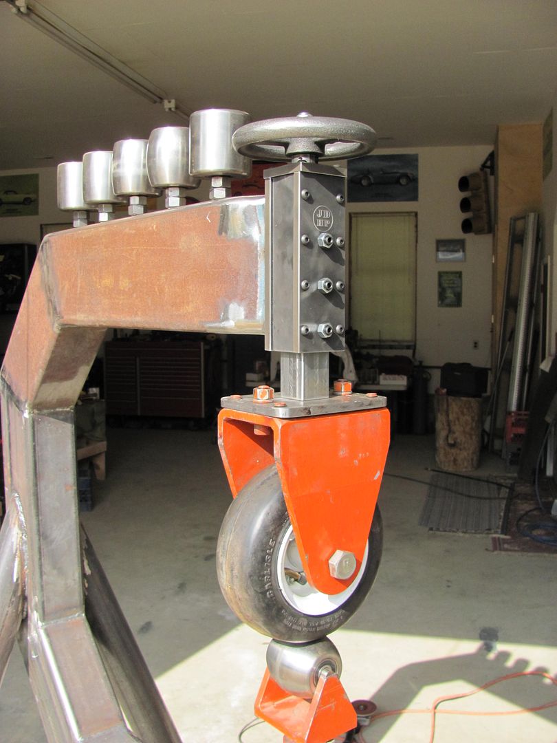
Having just set up my bead roller with the skateboard wheel for tipping, I thought to use this with a beading die to form the tighter radius.
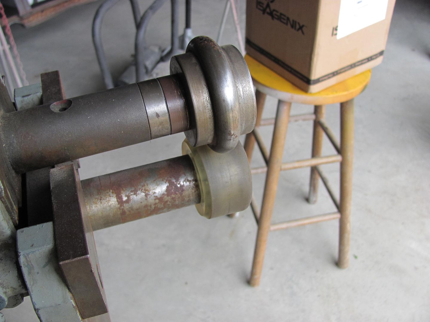
Here's the results of "rolling" the panel
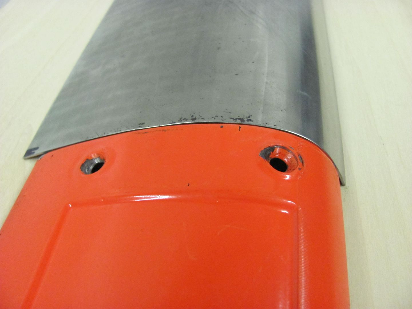
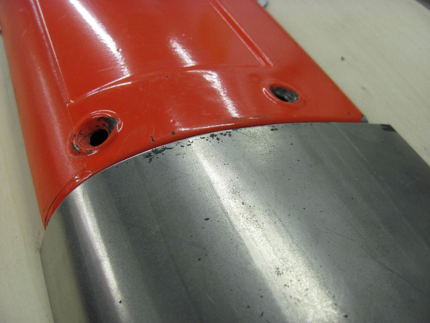
The panel has about an 1/8" lip around the perimeter, so the radius die was changed out to one for tipping.
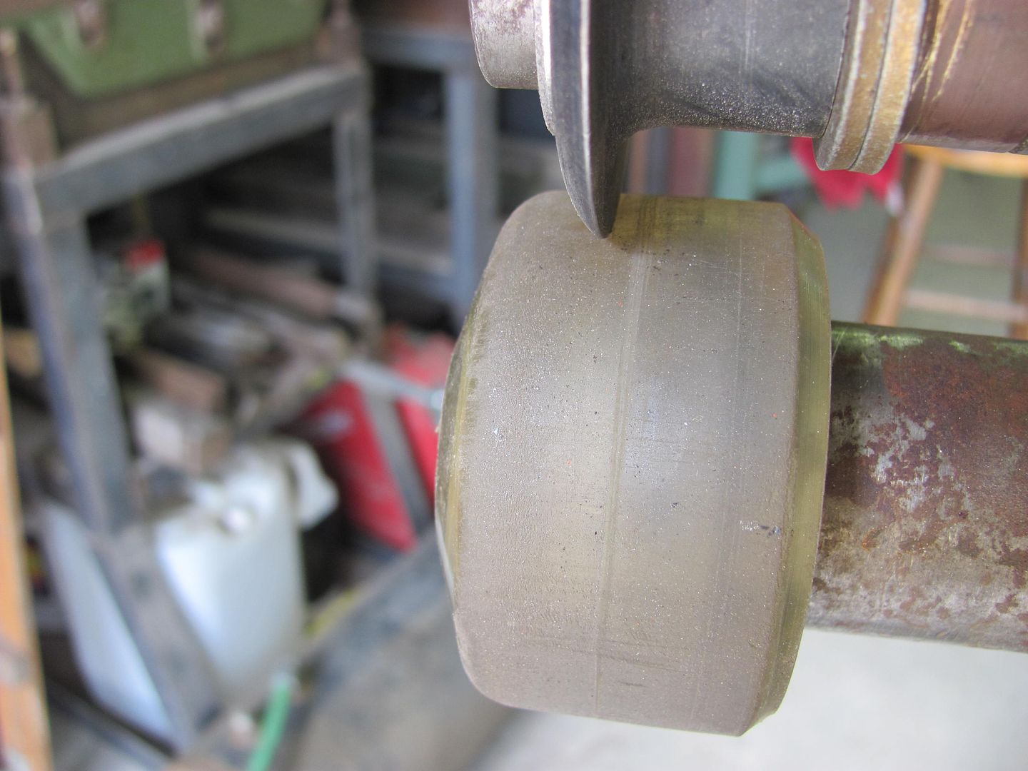
With only just over 1/8 of extra to tip the flange, this process was not that effective. Hindsight, about 1/4 left over and trimmed afterwards would have been more effective. But since the panel matched so well, lets try other persuasive devices.
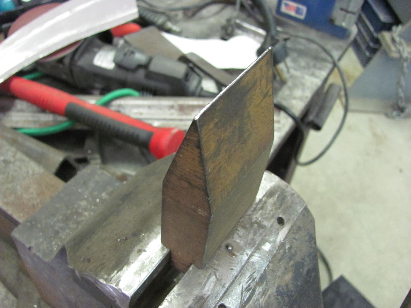
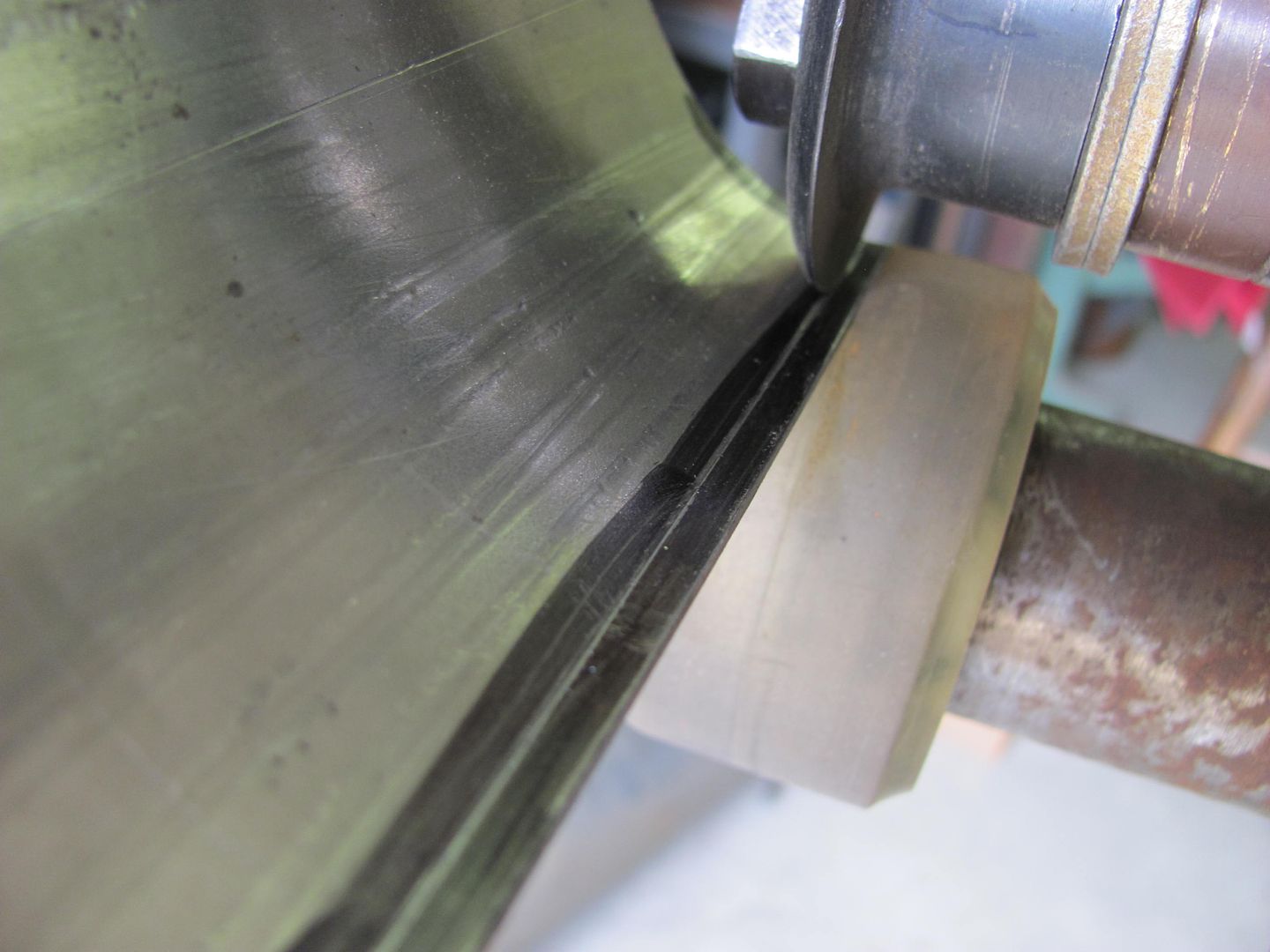
The tipping wheel did do an adequate job of marking the crease location....
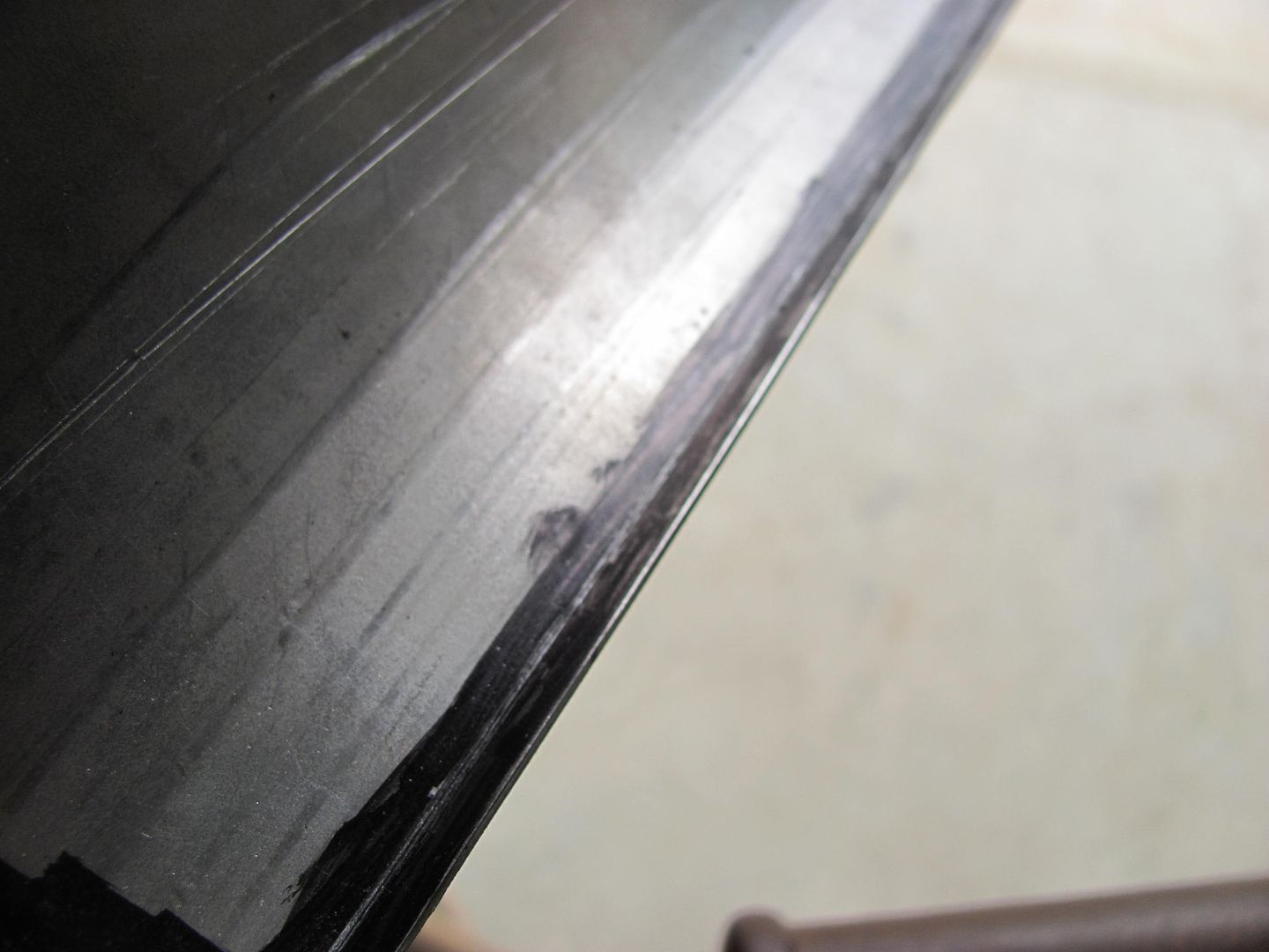
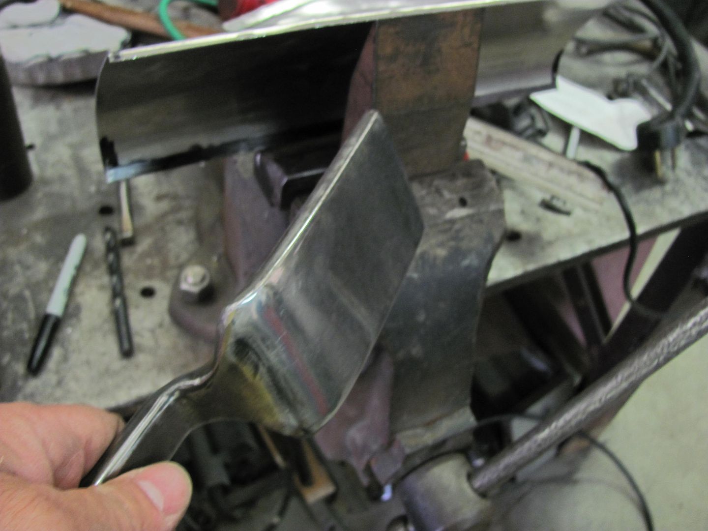
And the "vice anvil" and a slapper was used to fold the straight lip over to a 90....
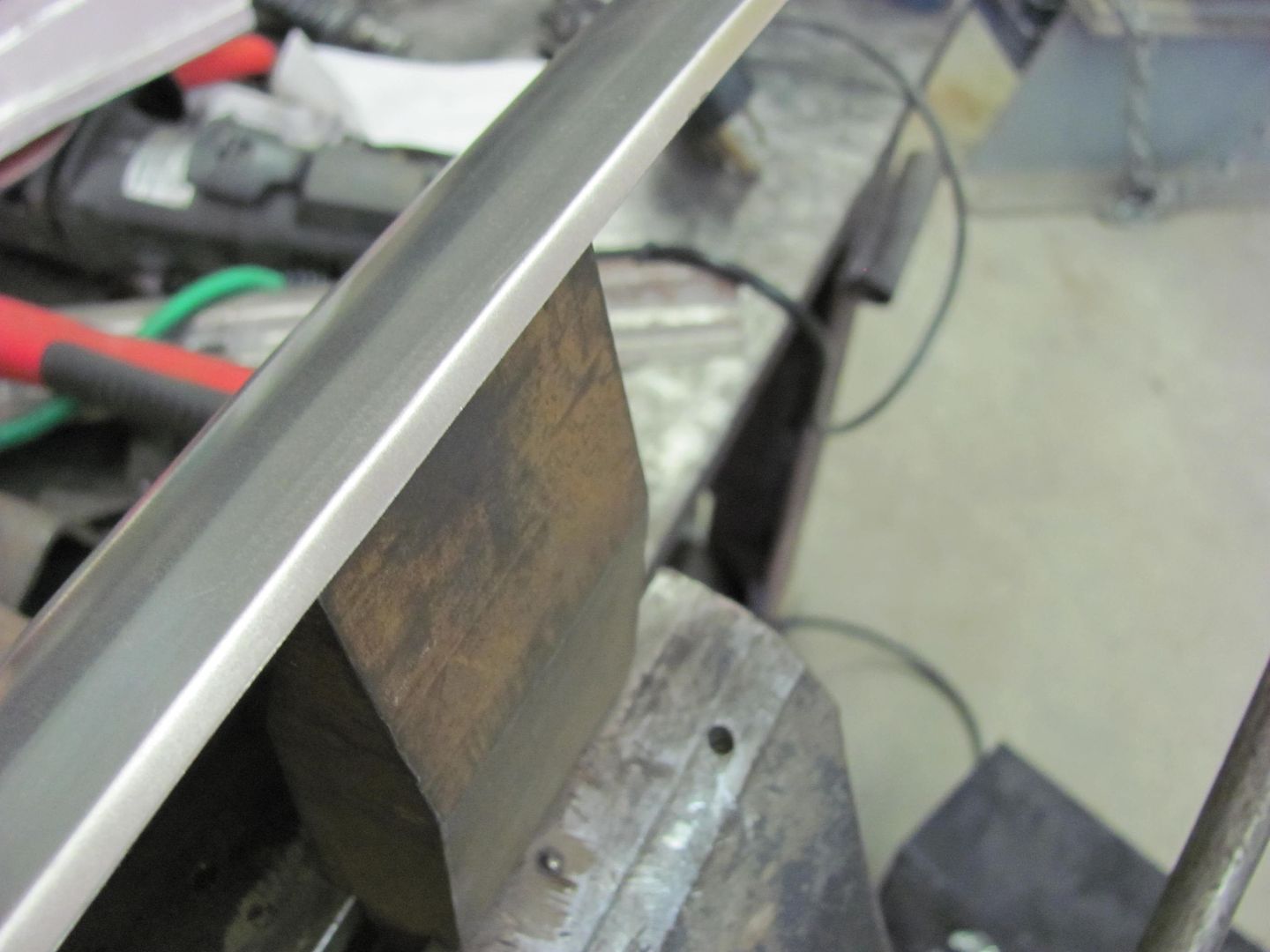
A different anvil was chosen for the radiused edges...
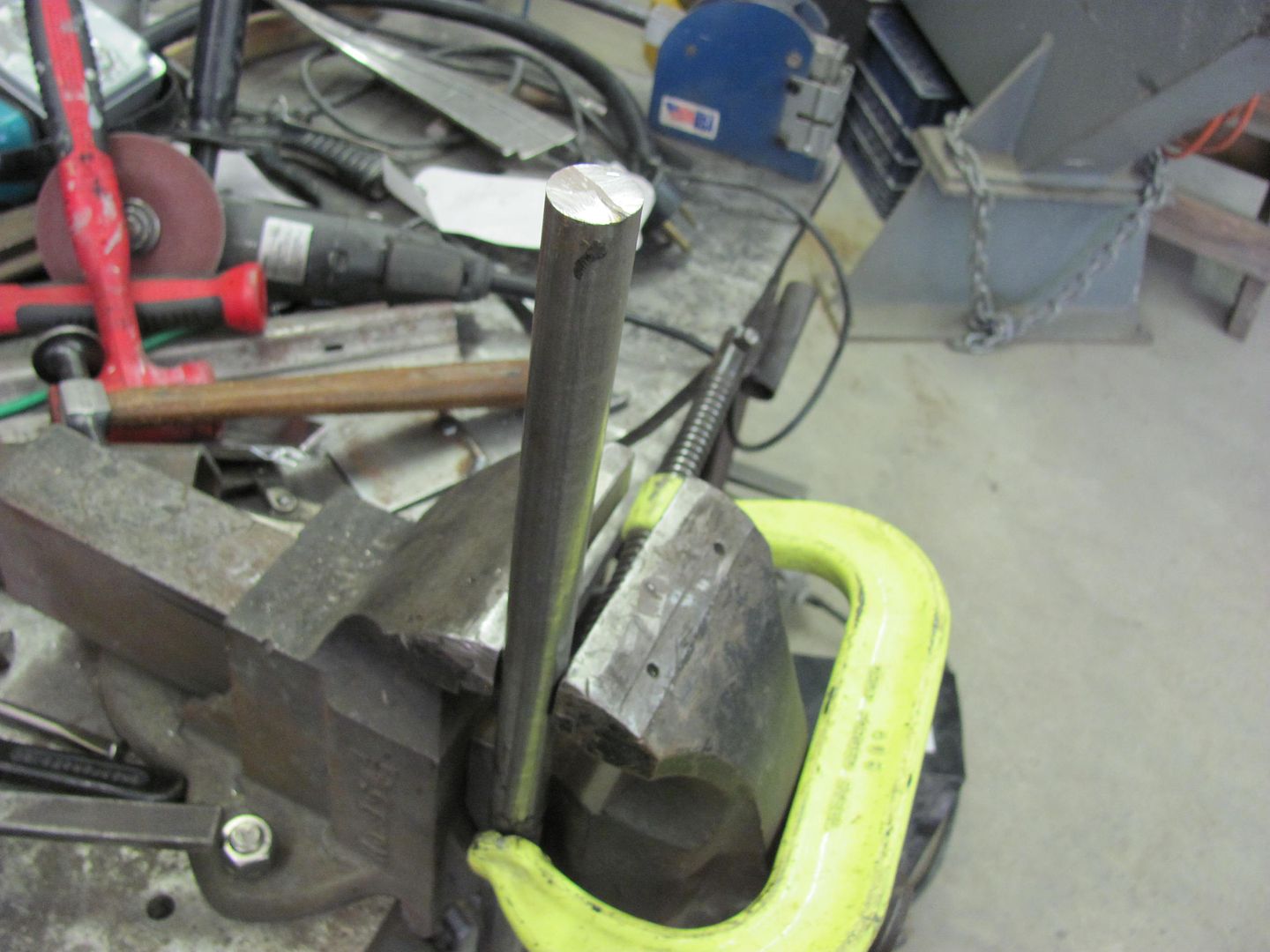
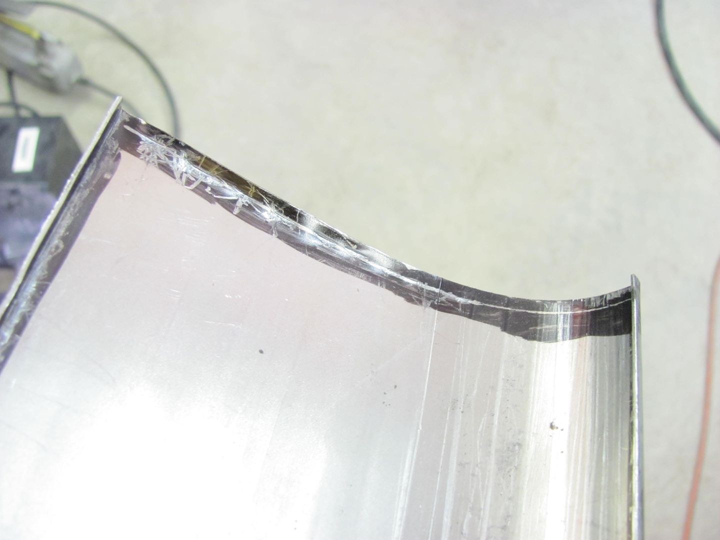
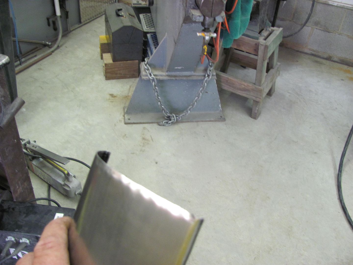
And a punch used to form the 4 corner radiuses...
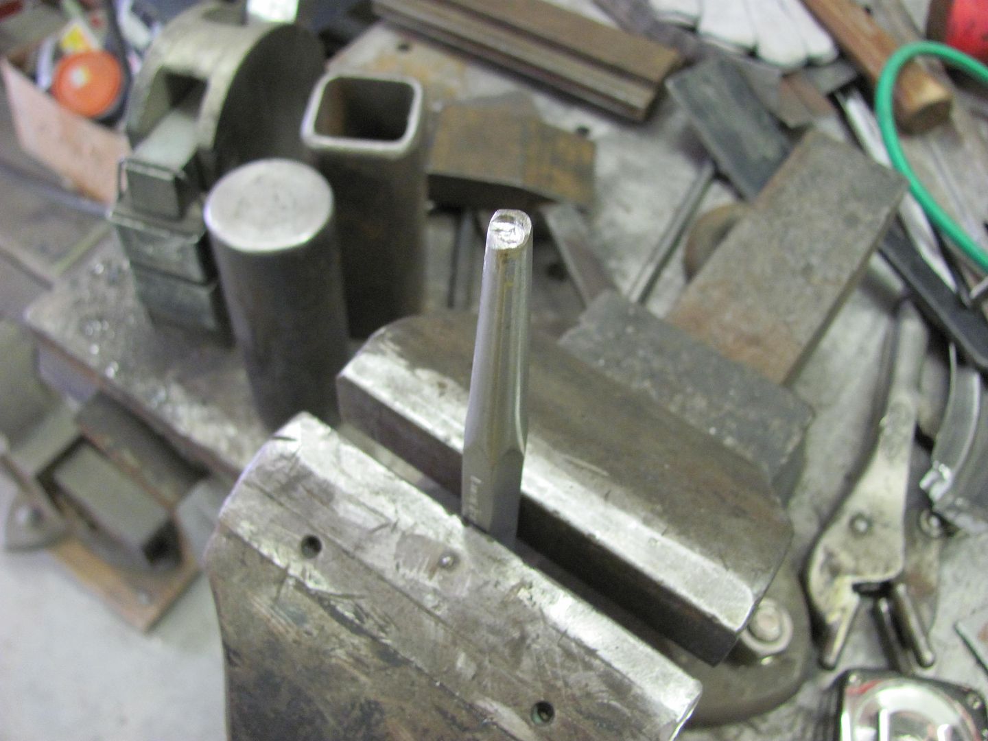
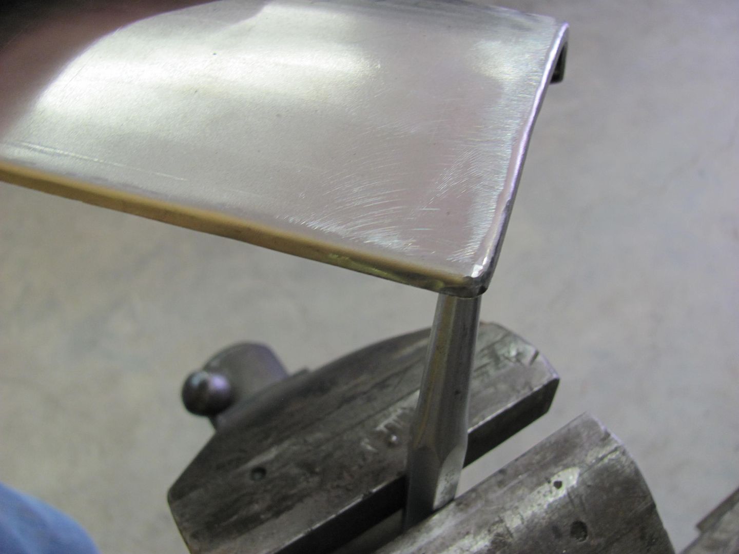
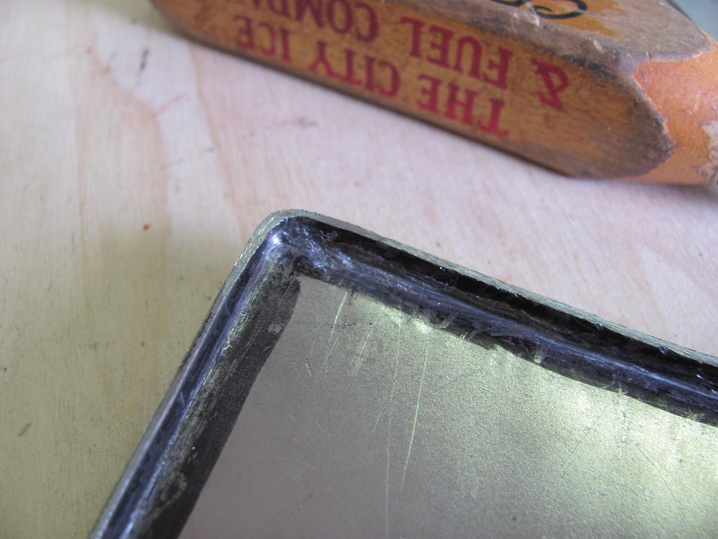
And once complete, the comparison.........
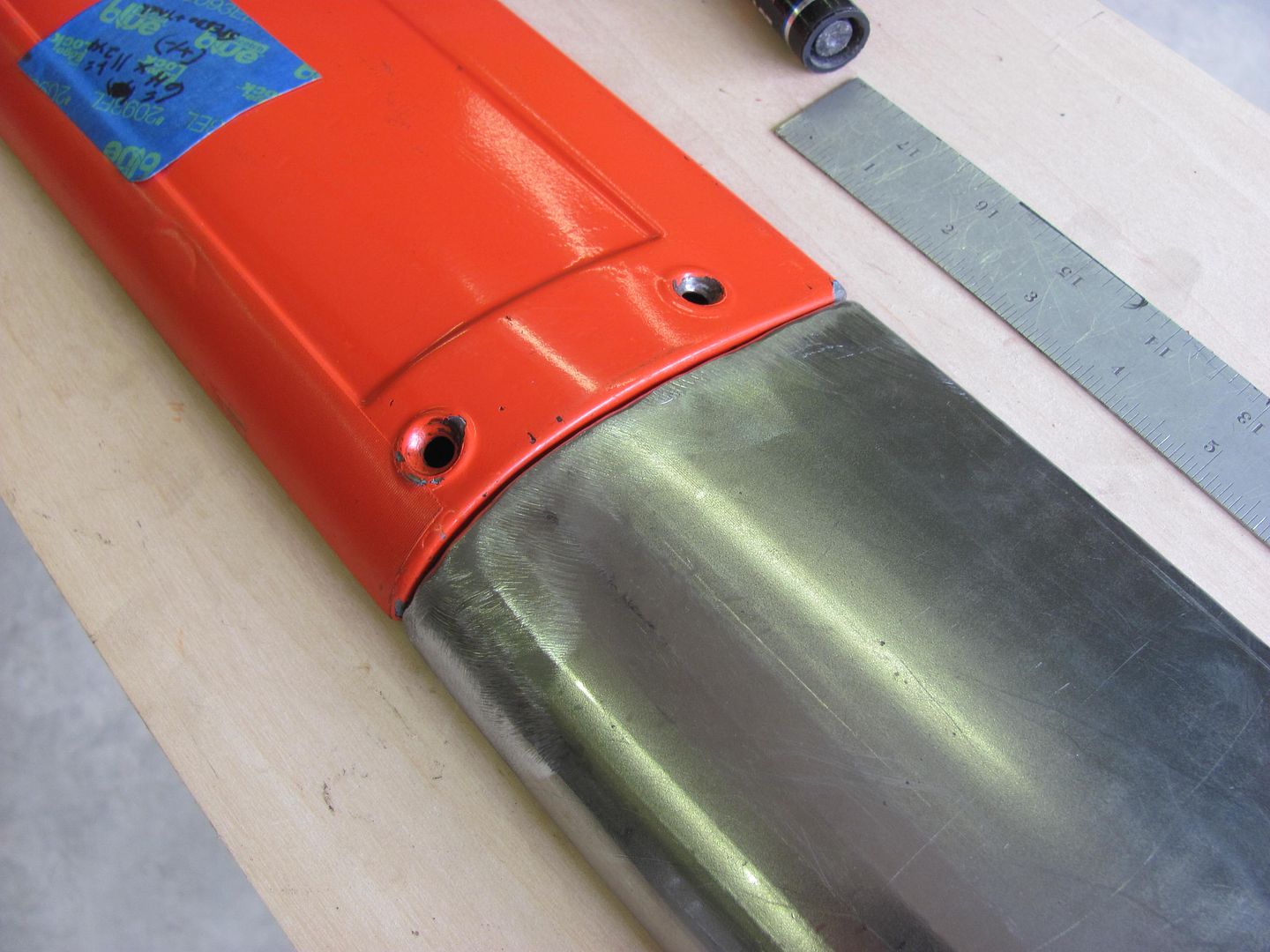
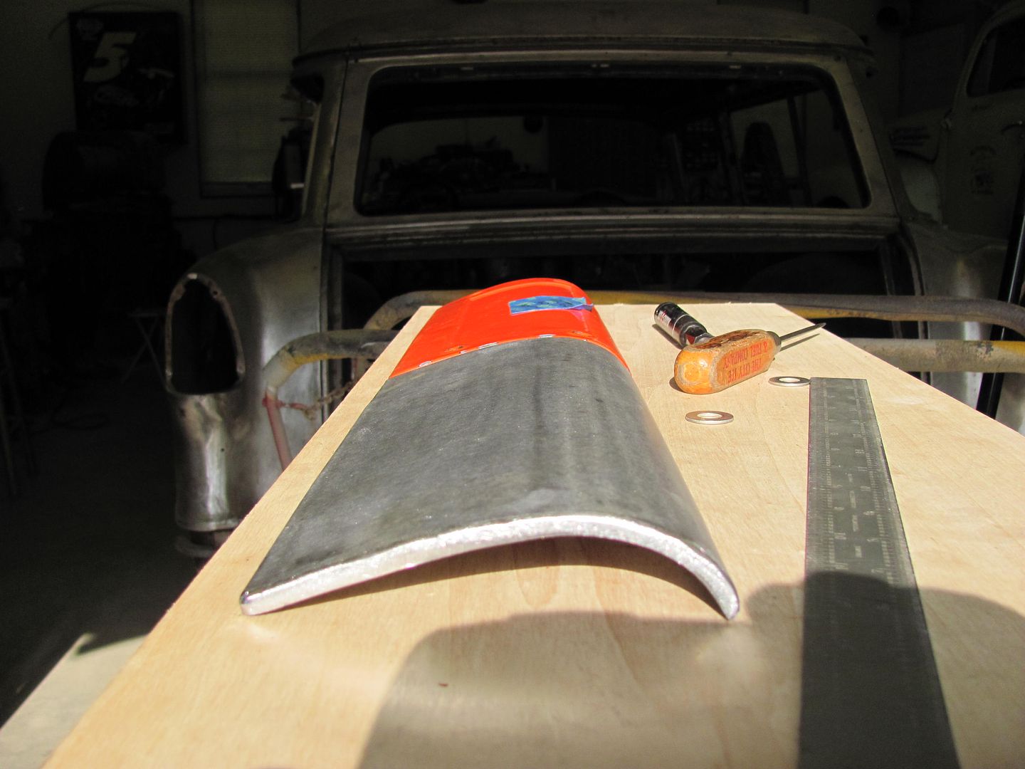
Then the same process was used for the upper plate. The folded edges on this will make it match the lower panel a bit better and make it look more as an original piece...
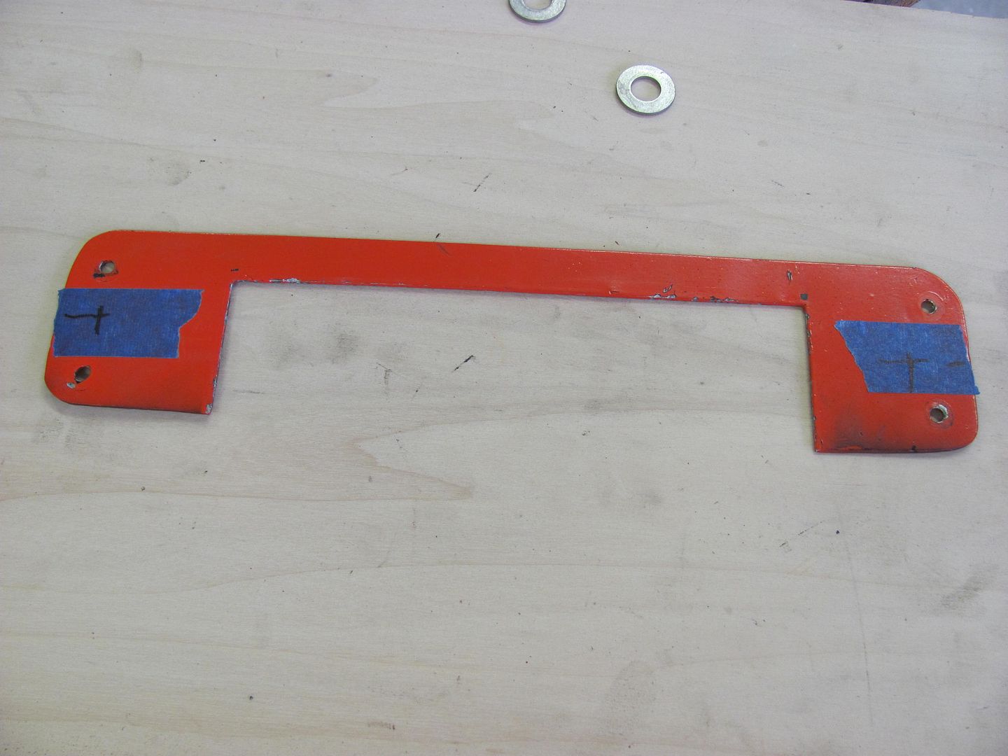
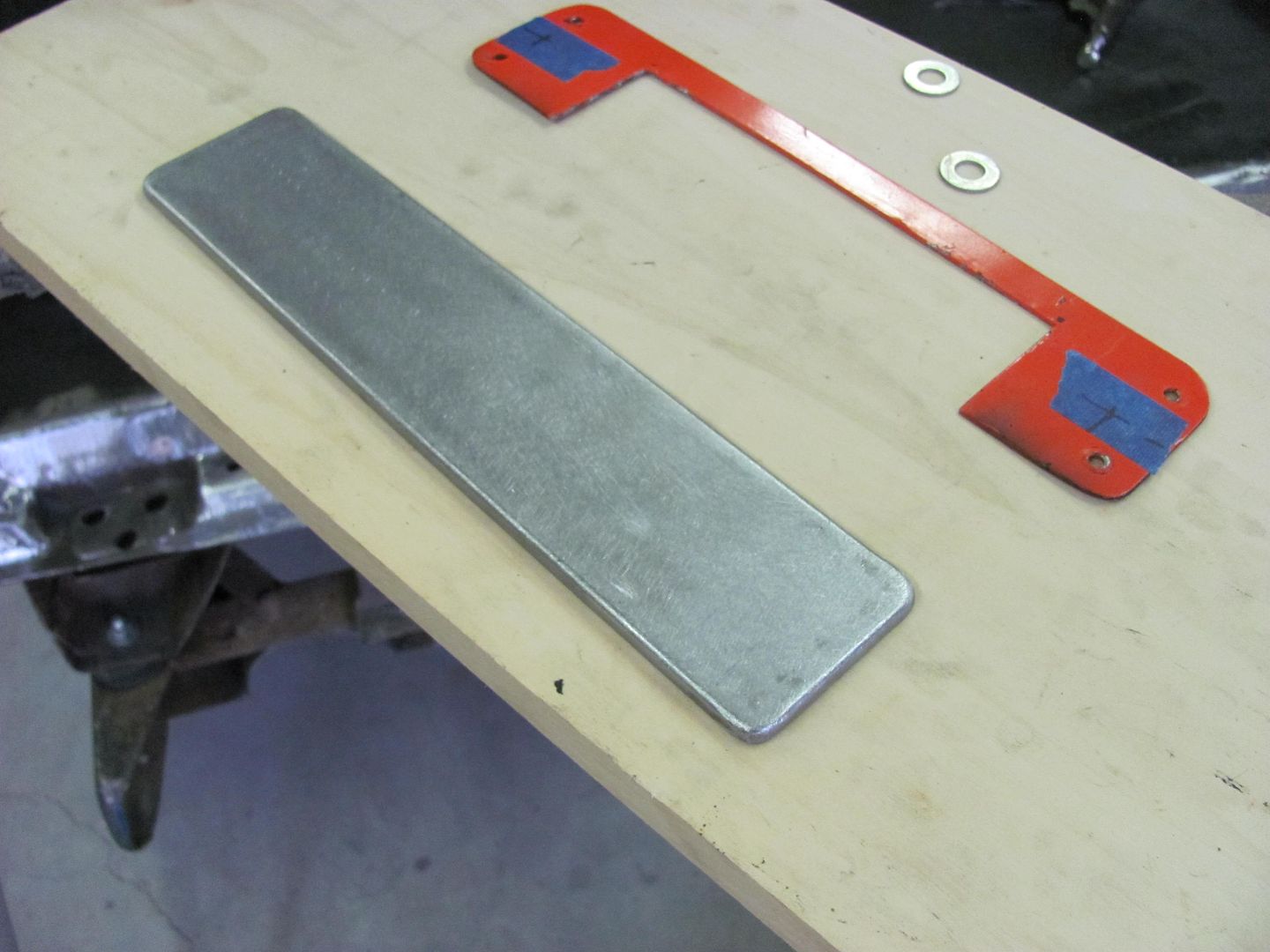
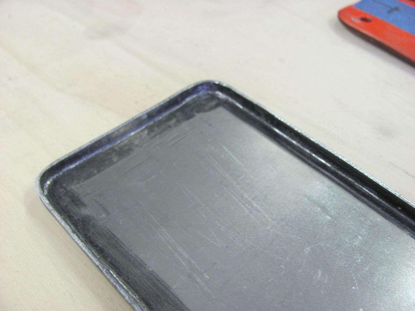
And the two together...
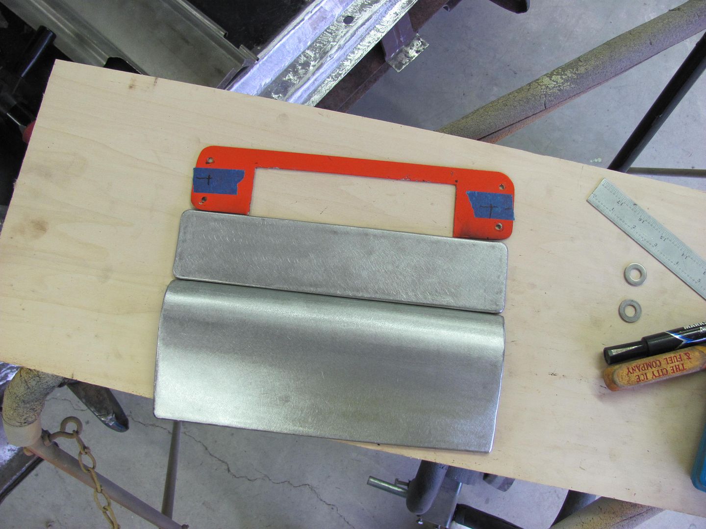
For now, we are leaving the mounting holes out. It may even get some studs welded on the back side, for a clean look. But we'll cross that bridge when we get there.
|
__________________
Robert
|

|

|


