 |
|
|
#26 | |
|
Senior Member
 Join Date: Jul 2009
Location: Athens, AL
Posts: 499
|
Re: Gear ratio question
Quote:
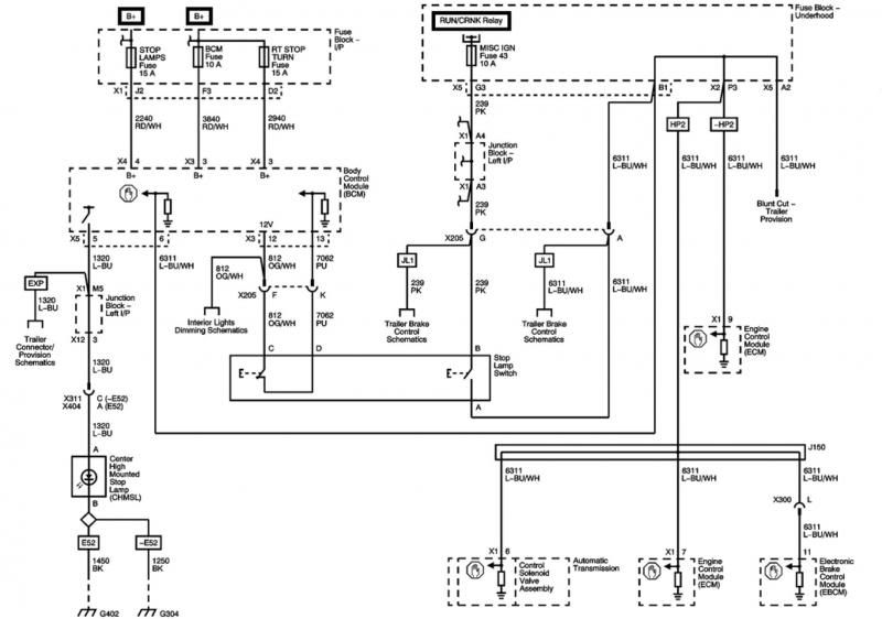
If an input (such as the brake signal input) is left disconnected, it is said to be "floating" and is in an undefined state that is neither high nor low. The brake switch only has two states, it's either on or off. For the ECM to verify that the switch is working, it needs to see a change between the two states (remember that a floating input is not a valid state). So, the ECM can not verify that the switch is working unless it "sees" the state flip from ground to 12V (low to high). Now, you may be saying that's good and all, but why does the ECM care that the switch is working? The answer is simple. It's a safety measure. While your life doesn't depend on your torque converter locking up, The Gen IV ECM uses the same switch for turning off cruise control. It's pretty important to verify that the brake switch is working in both the "on" and "off" states before locking in that fancy DBW throttle body at 75 MPH on the freeway. I hope that helps. Let me know if it still doesn't make sense. |
|
|
|

|
|
|
#27 |
|
Registered User
Join Date: Jul 2003
Location: Cypress, Tx
Posts: 4,005
|
Re: Gear ratio question
That is an absolutely perfect explanation! Thank you! Outstanding!
Now the only other question is how do we know/verify that the ECM wants to see ground to know that it can tell the Tcm to engage the TCC? How do we verify that it doesn't want to see 12 volts to know that it can engage the TCC. How do we know we don't have it backwards on the newer 6l80?
__________________
1972 C20 Suburban- Big Blue Betty '56 Chevy Bel Air Sedan- Frame up Restoration -What would you attempt to achieve if you knew you could not fail?- -I Refuse To Tiptoe Through Life, Only To Arrive Safely At Death's Door- R.I.P. EAST SIDE LOW LIFE |
|
|

|
|
|
#28 | |
|
Senior Member
 Join Date: Jul 2009
Location: Athens, AL
Posts: 499
|
Re: Gear ratio question
Quote:
 . So, in this instance, splice the light blue/white wire from the ECM into the white wire coming off the stock brake switch. No relay is needed and the stock 2 pin brake switch will work fine. Also, no resistor is needed as long as you don't have LED tail lights. . So, in this instance, splice the light blue/white wire from the ECM into the white wire coming off the stock brake switch. No relay is needed and the stock 2 pin brake switch will work fine. Also, no resistor is needed as long as you don't have LED tail lights.
|
|
|
|

|
|
|
#29 | |
|
meowMEOWmeowMEOW
Join Date: Sep 2009
Location: MKE WI
Posts: 7,128
|
Re: Gear ratio question
Quote:
Just a good talking point, thanks for bringin it up.
__________________
'66 Short Step / SD Tuned / Big Cam LQ4 / Backhalfed /Built 4l80e / #REBUILDEVERYTHING  |
|
|
|

|
|
|
#30 | |
|
Registered User
Join Date: Dec 2002
Location: Cactus Patch So. Az
Posts: 4,749
|
Re: Gear ratio question
Quote:
__________________
53 TuTone Extended Cab 350 4-Spd 3:08 (SOLD) 53 Chevy Moldy pearl green ZZ-4 4L60E 9" 3:25 55 GMC 1st Black Mll (ZZ4) ZZ6 TKO 600 5 sp 3:73 62 Solidaxle Corvette Roman Red (327 340hp 4spd 3:36) C4 & C5 suspension tube chassis LS 3 4L70E 65 Corvette Coupe 327 350hp 4spd 4:11 78 Black Silverado SWB (350/350) 5.3 & 4L60E 3:42 2000 S-Type 3.0 (wife cruiser) 2003 GMC SCSB 5.3 4L60E 3:42 |
|
|
|

|
|
|
#31 |
|
*************
 Join Date: Apr 2005
Location: Pensacola, FL
Posts: 17,858
|
Re: Gear ratio question
Quote:
Dayj1 - thanks for the great circuit breakdown and your insight. I have a 2013 Camaro SS 6L80 and assume it is the same as the diagram you posted. I do have LED tailights and plan on using a relay and a 1K ohm/1 watt resistor for the pull down circuit. Do you see any problem with the setup? Thanks, Rob
__________________
Rob - https://www.instagram.com/hart_rod_c10 As Iron Sharpens Iron, So One Man Sharpens Another. Proverbs 27:17 FOR SALE: DBW pedal bracket - http://67-72chevytrucks.com/vboard/s...d.php?t=651123 FOR SALE: Hood Brackets http://67-72chevytrucks.com/vboard/s...d.php?t=679945 1987 Silverado SWB - 34.5K original miles http://67-72chevytrucks.com/vboard/s...d.php?t=801834 1969 SuperBurb - http://67-72chevytrucks.com/vboard/s...d.php?t=200387 1968 Farm truck - http://67-72chevytrucks.com/vboard/s...d.php?t=358692 1968 SWB - http://67-72chevytrucks.com/vboard/s...d.php?t=551258 1948 Chevy - http://67-72chevytrucks.com/vboard/s...=122164&page=3 |
|
|

|
|
|
#32 | |
|
Senior Member
 Join Date: Jul 2009
Location: Athens, AL
Posts: 499
|
Re: Gear ratio question
Quote:
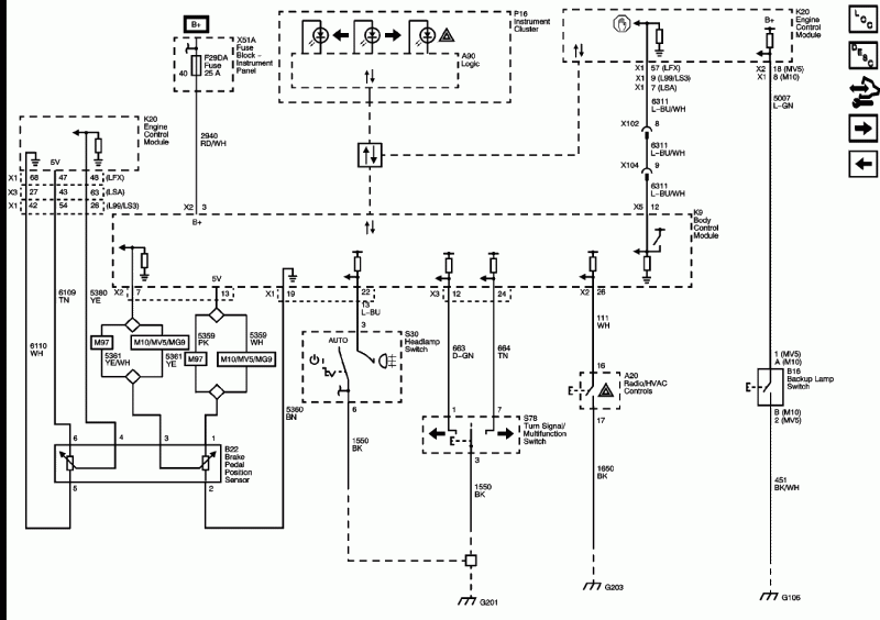
The schematic for the Camaro brake light control is below. It's actually quite a bit different than the Escalade diagram above. The Camaro uses a variable resistance pedal sensor instead of a conventional switch. The brake pedal sensor outputs to the BCM and the BCM "talks" to the ECM over the same pin as the Escalade (7 or 9 depending on RPO code). From there, the ECM communicates with the TCM over the CAN bus just like the Escalade. I'm not sure why the Camaro needs a sensor to determine the exact position of the brake pedal. Maybe it's used by the traction control system? For the purpose of TCC lockup, though it looks like you just need to provide 12 volts to the ECM with the brake pedal applied and ground when not applied just like the Escalade. I hope all that helped. 
|
|
|
|

|
|
|
#33 |
|
Registered User
Join Date: Jul 2003
Location: Cypress, Tx
Posts: 4,005
|
Re: Gear ratio question
Dayj1, can I just say that YOU DA MAN!!! Thank you so much for your help and your invaluable insight! You have cleared up what has been a very confusing issue!! Thank you again!!!
Shawn
__________________
1972 C20 Suburban- Big Blue Betty '56 Chevy Bel Air Sedan- Frame up Restoration -What would you attempt to achieve if you knew you could not fail?- -I Refuse To Tiptoe Through Life, Only To Arrive Safely At Death's Door- R.I.P. EAST SIDE LOW LIFE |
|
|

|
|
|
#34 |
|
Registered User
Join Date: May 2013
Location: Houston Texas
Posts: 713
|
Re: Gear ratio question
WOW!! Lots of good info the past day! I just got back an email from 150tunes stating all I had to do for the 2011 5.3 w/6L80 was hook the harness brake wire to the vehicle brake wire so that the harness wire receives power when the peddle is pressed, just like jday1 stated. I guess I can get rid of the relay now.
Thanks for all the help everyone, good learning lesson on this one! |
|
|

|
 |
| Bookmarks |
| Thread Tools | |
| Display Modes | |
|
|