
 |
|
|
#26 |
|
Registered User
Join Date: Dec 2000
Location: Boise, Idaho
Posts: 6,003
|
Re: Welding body panels
Which are you asking about? The shield I am using for gas welding simply uses a tinted shield, remember it's gas welding so you it's a #6 shade and you can see thru it just like sun glasses.
 The "Accustrike" helmet I use for MIG welding has a chin controlled shield. Check out this video to see it at work. https://www.youtube.com/watch?v=_xIO-7pcQjk Here's another video showing it working. https://www.youtube.com/watch?v=SSgBSx4GjGc Brian
__________________
1948 Chevy pickup Chopped, Sectioned, 1953 Corvette 235 powered. Once was even 401 Buick mid engined with the carburetor right between the seats! Bought with paper route money in 1973 when I was 15. "Fan of most anything that moves human beings" |
|
|

|
|
|
#27 | ||
|
Registered User
Join Date: Jan 2013
Location: Leonardtown, MD
Posts: 1,648
|
Re: Welding body panels
Quote:
Same user name everywhere, except where forum software does not permit characters (&) . Then it's MPandC.  Thanks for sharing the link, quite a bit of info in there.. Quote:
I'll add some comments, but please don't take this as criticism. I've done some of the same things myself, and it's all part of the learning curve. My intent is to pass on some of the things you may see as you continue with your panel install, so you can better understand what it occurring that you can deal with any of the issues (reactions) that crop up. Fitment looks good on the panel, except for the added strip on the end. I will say that some panel movement does tend to occur as welds shrink and push/pull at the surrounding area. With any added strip like that, you may find is easier to better keep the panel shape in check if you weld the strip onto the panel off the vehicle, do the weld planishing and dressing, re-trim to fit the opening and then weld to the vehicle. Having a strip in between two panels puts two weld seams in close proximity, which compounds those shrinking effects in a confined space. Not that they can't be dealt with, but it may be more of a challenge. Having the panel off the vehicle to correct any mis-cuts allows better opportunity for any panel deformity to be worked off the end of the panel. Welded in as you've shown with the strip between two panels will tend to lock things in place, where any deformation that may occur is more work to get things back in check. (food for thought) At this point I'm not suggesting to cut anything out, it's more of an awareness thing so you can better monitor panel movement. Most quarter panel installs involve a somewhat flat crown in both the horizontal and vertical directions. Regardless of appearance, all body panels will have crown in at least one direction to help hold the shape of that panel. A flat sheet of metal has no support and will flap in the breeze, so ALL panels will have crown somewhere. If we were to look at your top seam along the weld in a cross-section view (top-down) you would see that despite appearing flat, that panel actually has crown from front to back. It looks like a slight arc. Now, anytime you apply the heat from welding, you are going to get a shrink as that weld cools. When we weld one dot at a time, each and every dot is going to pull at the metal around it, from all directions, causing a shrink. Once you've added all those shrinks from all those weld dots together, along the entire weld seam, it adds up to a substantial amount of shrink such that what used to look like an arc is now more closely resembling a straight line. So given a weld seam like that, without any planishing to counteract the shrinking, you will see the panel pulling inward, as the crown at the weld is shrinking. Looking at the panel as a whole, unchecked shrinking would appear as a pronounced valley, where the weld seam is shrinking and pulling the adjacent panels along for the ride. On the panel fitment, you will likely find that the sharp 90 degree corners on the patch will help to add a bit of distortion. As your welds shrink, a tight inside corner gets those effects from two different directions, where the shrinking effects will compound in the inside corner, normally as a pucker that is a bit challenging to remove. On the corners a large sweeping radius helps to balance out the shrinking effects on either side of the weld, where the planishing efforts don't need to focus on puckers or deformity on one side only. As to addressing the welds: I have found that due to the manner in which each weld dot shrink pulls from ALL directions, you will have better luck in planishing to remove said shrinking effects if you can planish the weld dots while they are singular, sitting all by their lonesome. This will more effectively STRETCH that weld dot back out in all directions. And by stretching as you go, you help eliminate the panel being pulled into a valley on those long welds. As far as tacking the panel in place, (FYI) I normally would start the tacks at one end and work toward the other. I know many people will tell you to skip around to minimize heat buildup, and I have been one of those. But if you tack one end and then move to the opposite end, you run a greater risk that one panel may have more material than the other due to misalignment. Once things get all tacked up, this results in a panel bulge on one side of the weld. So tacking from one end and working progressively to the other will help to eliminate this by being able to align the panels together as you go. Now that the panel is tacked and weld dots are spaced about (2 or 3"), go back and planish each weld dot individually, to add a bit of stretch. At this point, I use a 3" cutoff wheel to grind down the dots to just above flush. This gets them out of the way for planishing the next sets of dots, and by leaving them just above flush, you can do the final cleanup with a roloc sander all at once. By trying to grind things down to perfectly smooth after each, you run a greater risk of inadvertent sanding of the metal to the sides of the welds, which may thin and weaken the panel. So I hold off on this until the end. For your grinding disc, I prefer to use cutoff wheels about 1/16 thick. This gives a much smaller contact area than most any other method, so you will have less heat buildup from the grinding process. It also gives the best unobstructed view of what you're doing, so again, less chance of inadvertent abrading/thinning of the parent metal to the sides of the weld. Other grinding methods, such as using a flap disc, hide most of what you're doing, and generate too much heat. Here is a link showing the grinding method on a plug weld, again, sanding on a weld seam I would wait until the end. https://www.youtube.com/watch?v=V2WHT_zMOE8 Once these initial welds are planished and ground down just above surface, then continue, adding a weld between each one until your welds are spaced about 1" apart. At this point (still planishing and grinding after each time) instead of hitting the center between for weld location, start overlapping by about 1/3 of the last welds. By overlapping, you will have less risk of missed spots or pin holes. Continue with the weld, planish, grind, repeat until the seam is done. I typically weld from start to finish using weld dots only, none of the longer passes at the end, in order to keep everything consistent throughout the process. For the cutoff wheels, I spend the extra coin and get ones rated for stainless steel. This makes them last longer and put less of that brown haze in the air that you see from the cheap HF or swap meet specials. By the time you figure out the cost of how quickly the cheap ones wear away, you haven't saved a thing. For the roloc sanding disc, the bulk of the welds are being removed by a cutoff wheel, we are only dressing what little remains of the weld and blending that into the parent metal. This is easily accomplished using a 60 or 80 grit, that should be as coarse as you need to go..
__________________
Robert |
||
|
|

|
|
|
#28 |
|
Registered User
Join Date: Jan 2013
Location: Leonardtown, MD
Posts: 1,648
|
Re: Welding body panels
Forgot about the welding wire.. SS will tend to have a higher tensile characteristics than the mild steel wire, so I wouldn't advise using it on sheet metal as planishing efforts may be more difficult or may show some cracking. I have recently changed from ER70S-6 wire to ER70S-7 wire, and have found the higher manganese content to improve wetting/flow and decrease proud height. In the singular weld form (one dot as opposed to a gap filling blob) it has shown to be slightly softer for easier planishing as well as grinding. Lower proud means less consumable used in the grinding process, but still sufficient proud on either side of the panel for effective planishing. Here's some samples of the -7 in a practice piece after setting up the machine, note the minimal proud height and consistency in weld size from front to back, works well for planishing singular welds without touching the panel..
Front of panel... 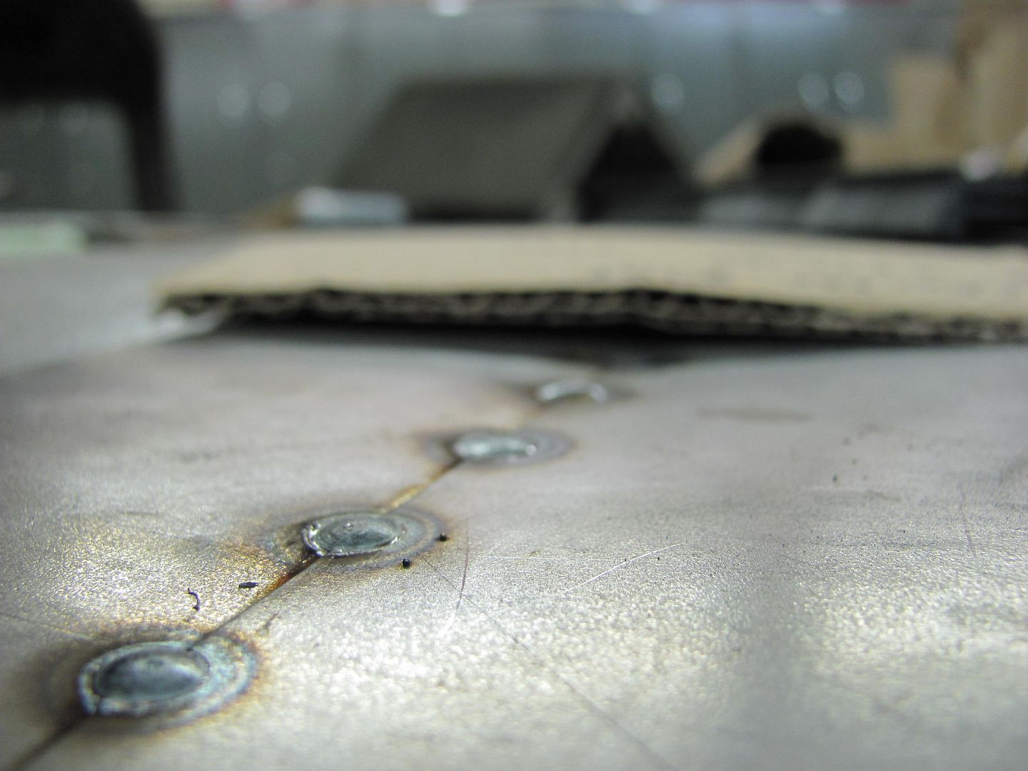 Rear of panel.... 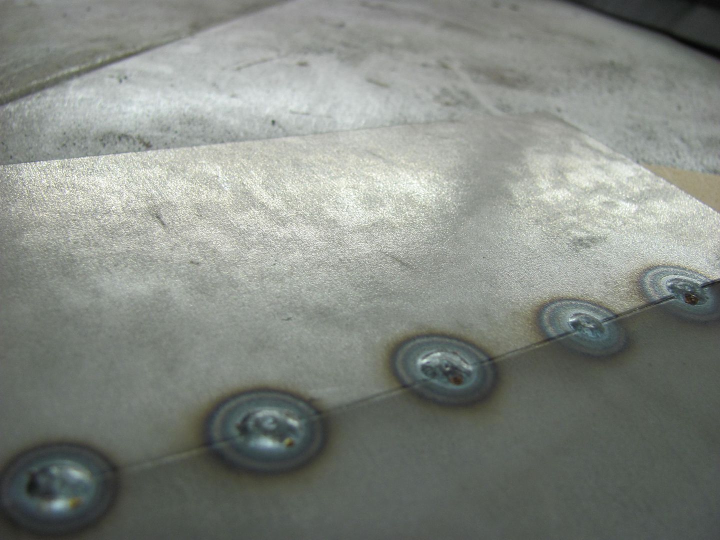 Here's a couple pics showing the grinding and overlap process.. All clamped up... 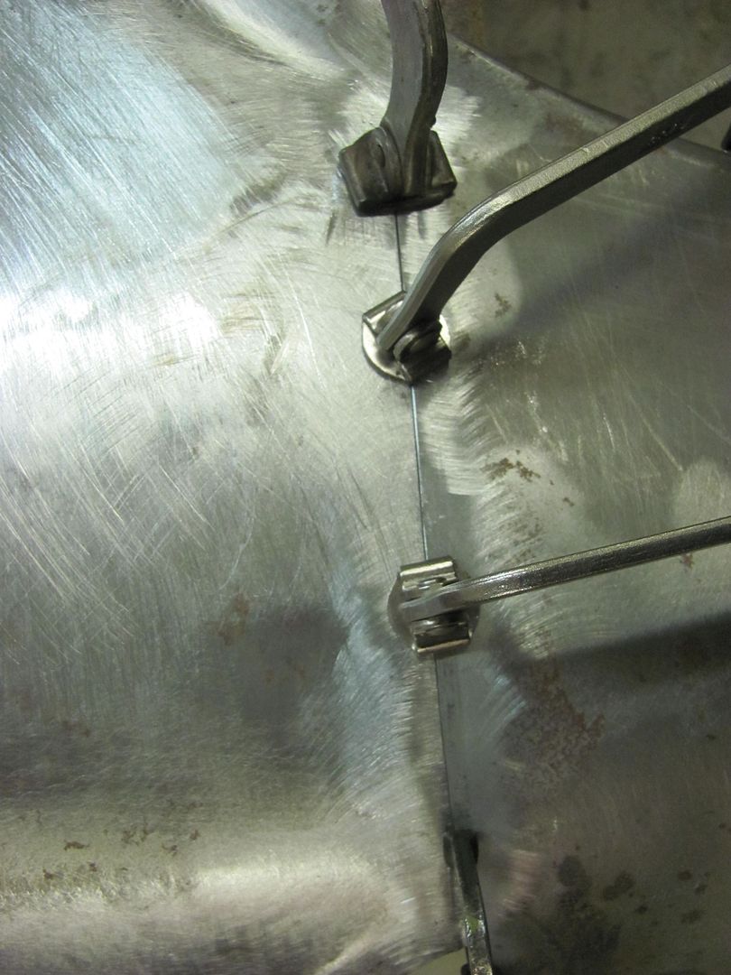 First set of tacks... 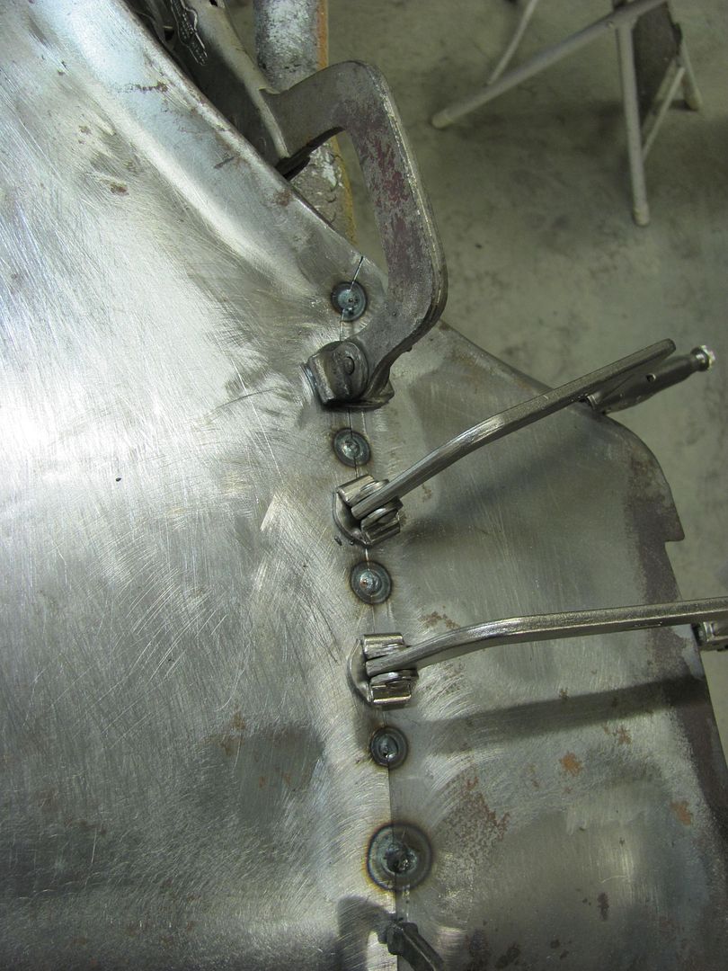 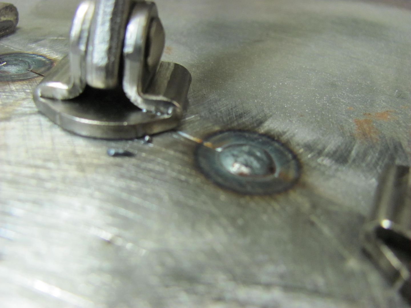 Weld penetration, the back side.... 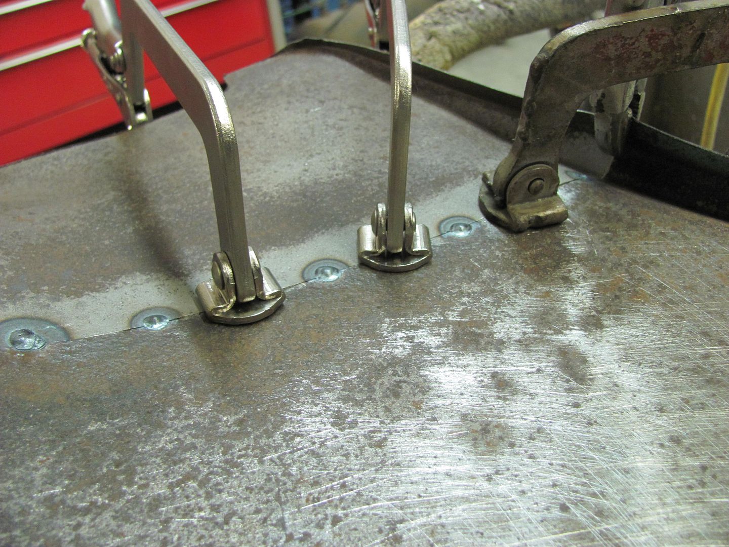 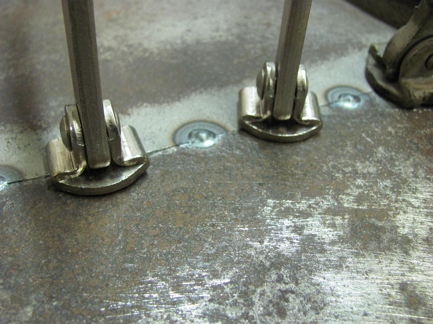 Weld, planish, grind, overlap, repeat... 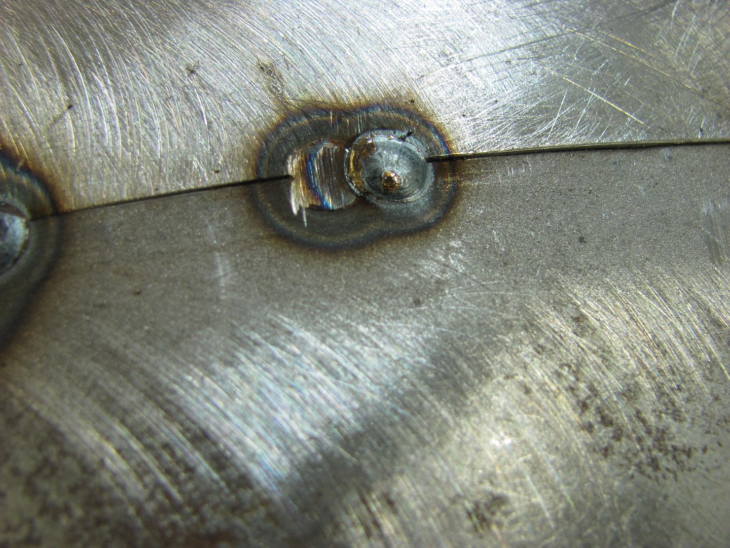 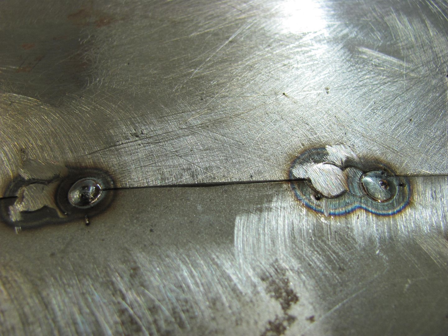 Planishing as you go helps to keep the panel's shape in check... 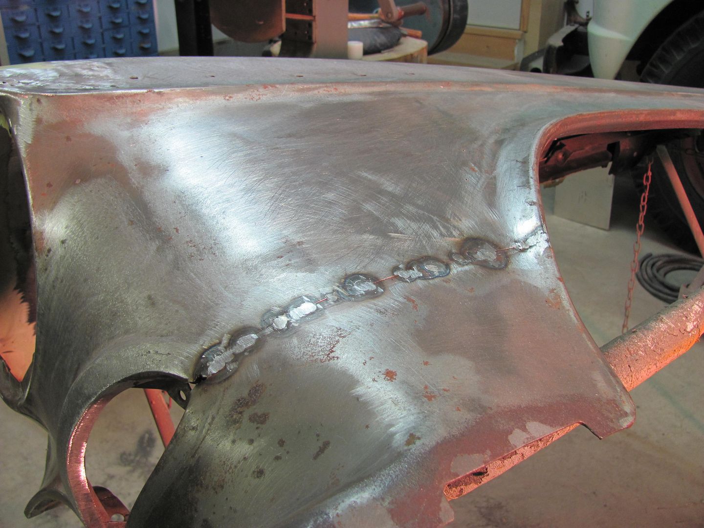 Still needs a bit of metal bumping but not too bad overall.. 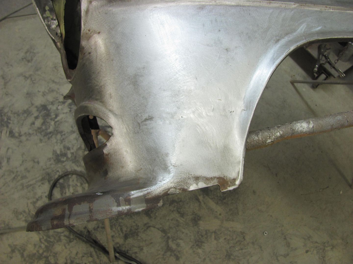 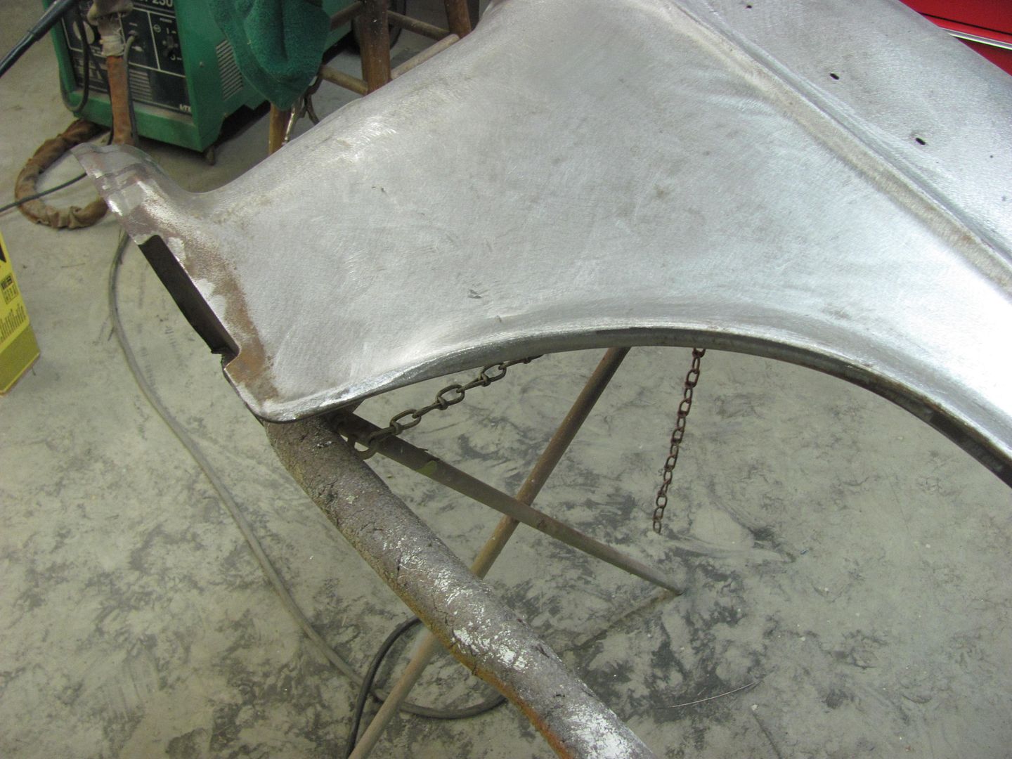
__________________
Robert |
|
|

|
|
|
#29 |
|
Registered User
Join Date: Dec 2000
Location: Boise, Idaho
Posts: 6,003
|
Re: Welding body panels
Awesome stuff Robert.
 Brian
__________________
1948 Chevy pickup Chopped, Sectioned, 1953 Corvette 235 powered. Once was even 401 Buick mid engined with the carburetor right between the seats! Bought with paper route money in 1973 when I was 15. "Fan of most anything that moves human beings" |
|
|

|
|
|
#30 |
|
Registered User
Join Date: Jul 2009
Location: San Jose Ca
Posts: 2,871
|
Re: Welding body panels
You guys do amazing work.
__________________
David Used parts build: http://67-72chevytrucks.com/vboard/s...d.php?t=638991 My brother's Nova: http://www.67-72chevytrucks.com/vboa...d.php?t=727985 Rear suspension rework: http://www.67-72chevytrucks.com/vboa...d.php?t=750557 Instagram: myfabguy |
|
|

|
|
|
#31 |
|
Registered User
Join Date: Dec 2000
Location: Boise, Idaho
Posts: 6,003
|
Re: Welding body panels
What Robert shows you is with taking your time, proper fit of the panels, with proper time you can do this stuff too. The fit of the panels is the absolute most important part. It takes mad skills to do it fast like he probably does. But most anyone with enough time can do the same thing. Practice a little, you will find yourself doing stuff like that.
That is why he has posted this, so YOU can do it. Those close up photos of the panel fit, and quick hot welds, that detail he has provided you with is for you to do it too! Brian
__________________
1948 Chevy pickup Chopped, Sectioned, 1953 Corvette 235 powered. Once was even 401 Buick mid engined with the carburetor right between the seats! Bought with paper route money in 1973 when I was 15. "Fan of most anything that moves human beings" |
|
|

|
|
|
#32 | |
|
Registered User
Join Date: Jan 2013
Location: Leonardtown, MD
Posts: 1,648
|
Re: Welding body panels
Quote:
Brian, thanks for adding the clarification. Yes, guys, look at the details in the pictures, take in the "visual info", and just try to have some consistency in what you are doing. From panel fitment/trimming (no gaps), to panel alignment, to weld tack's size, to planishing, to grinding. It is ALL part of the process of welding in patch panels. By striving for consistency in all parts of the process, you will see better consistency in your results. Any one part that goes astray, and it throws off the rest. ie: in your panel fitment you mis-cut and have a wider gap in some spots. (been there, done that) This wider gap increases the likelihood of blowing holes as I've found it difficult to weld thin air.  It also means more fill for harder welds, harder to planish. More weld means more shrinking, so wide gap areas adjacent to tight gap areas will now start to show more panel deformation as the shrinking reactions are not consistent throughout the weld seam. So by focusing (becoming OCD of sorts) on consistency, you will improve your results. It also means more fill for harder welds, harder to planish. More weld means more shrinking, so wide gap areas adjacent to tight gap areas will now start to show more panel deformation as the shrinking reactions are not consistent throughout the weld seam. So by focusing (becoming OCD of sorts) on consistency, you will improve your results.
__________________
Robert |
|
|
|

|
|
|
#33 | |
|
Registered User
Join Date: Dec 2000
Location: Boise, Idaho
Posts: 6,003
|
Re: Welding body panels
Quote:
As an example my 17 year old son wanted to build one of these, a Lotus 7 copy. .jpg) Here is the frame to one, he said he couldn't make one of those.  He has done a little welding so I asked him pointing to one of the frames.... "Can you cut that little piece of metal off the end of a square tube to make that bracket" (letter "A") he said "Yes" "Can you drill a hole in it?" Yes he responded. "Can you weld it on?" he again responded "Yes". I asked him "can you cut that piece of tubing after measuring it with a measuring tape?" he responded "Yes" I asked him if he could drill those holes at "C", he said "Yes", well then I told him "You CAN make one of those frames from scratch".  If you break it down to small enough steps the only difference between washing and waxing a car and restoring one is the number of steps you have to do! Now I have to say, he never did make one, but it's not because he COULDN'T, we just decided to do something different. Which this dad was glad to hear being that car doesn't provide the occupants much safety. Brian
__________________
1948 Chevy pickup Chopped, Sectioned, 1953 Corvette 235 powered. Once was even 401 Buick mid engined with the carburetor right between the seats! Bought with paper route money in 1973 when I was 15. "Fan of most anything that moves human beings" |
|
|
|

|
|
|
#34 |
|
Registered User
Join Date: Sep 2011
Location: At the end of the road!
Posts: 282
|
Re: Welding body panels
I love the way Robert breaks it all down, it's the truth if you can break a large project down to small simple steps and learn to only follow those baby steps it will eventually all come together.I like to work on 2 panels or 2 seperate area's at once.I follow Robets advise and bounce back and forth tack there planish and grind tack the oppsite part I'm working on planish and grind.I will say this gets very boring but it does indeed work and it's proven to me that anything is possible by doing the smaller steps and taking my time only doing things that are reasonable in 1 days time...To better put it "why rush a good thing".If it works don't fix it....
__________________
Kev's-C-10 
|
|
|

|
|
|
#35 |
|
Registered User
Join Date: Apr 2003
Location: Indep, MO
Posts: 5,893
|
Re: Welding body panels
Dude, if Brian and Robert said it, believe it! I've used several of both their tips and it's helped me a bunch, and I've been around welding/fab and paint and body more than a couple days. Have a look at the s-box in my sig for how far out one can be and come back, using their advice.
__________________
Boppa's Old Yeller Truck Build, Old Yeller's New Heart! Project Buzz Bomb Flyin' Low! |
|
|

|
 |
| Bookmarks |
| Thread Tools | |
| Display Modes | |
|
|