
 |
|
|
#151 | ||
|
Registered User
Join Date: Dec 2009
Location: Independence Mo
Posts: 4,118
|
Re: 67-72 Electric speedo
Quote:
Quote:
As for how I put the S-10 face back on the clear plastic, if you don't touch the back side alot, it will be sticky enough to just stick back on. At least the ones I've done have worked out that way. You could put some glue on it or a few pieces of good quality tape on the edges since you can't see them once it's assembled. The tape I use for such things is the aluminum tape for sealing HVAC duct work in houses, which I'm sure you're familiar with! Also, don't worry about the "hijack", this thread is just information and your additions I think people will find helpful. 
__________________
My '72 short bed build. http://www.ls1tech.com/forums/conver...6-0-4l80e.html 5.3 swap into my RUSTY '71 C10 http://ls1tech.com/forums/conversion...71-c-10-a.html |
||
|
|

|
|
|
#152 |
|
Registered User
Join Date: Dec 2009
Location: Independence Mo
Posts: 4,118
|
Re: 67-72 Electric speedo
Here's the problem with the trip odometer. The re-set knob is just a touch too short. It's about 1-15/16" long, and needs to be close to 2-1/4". To remedy this I cut the knob and lengthened it with a small screw. You probably don't need a screw to do it, since you'll never really be putting much pressure on it, you could probably just drill it, put a short piece of a nail or something in it and glue it back together, but I had the stuff lying around and it's what I used.
These are the part's I used. A small drill bit, a 4-40 tap, and screw. Then I cut the knob off and sanded the end where I was going to be drilling the hole in it. 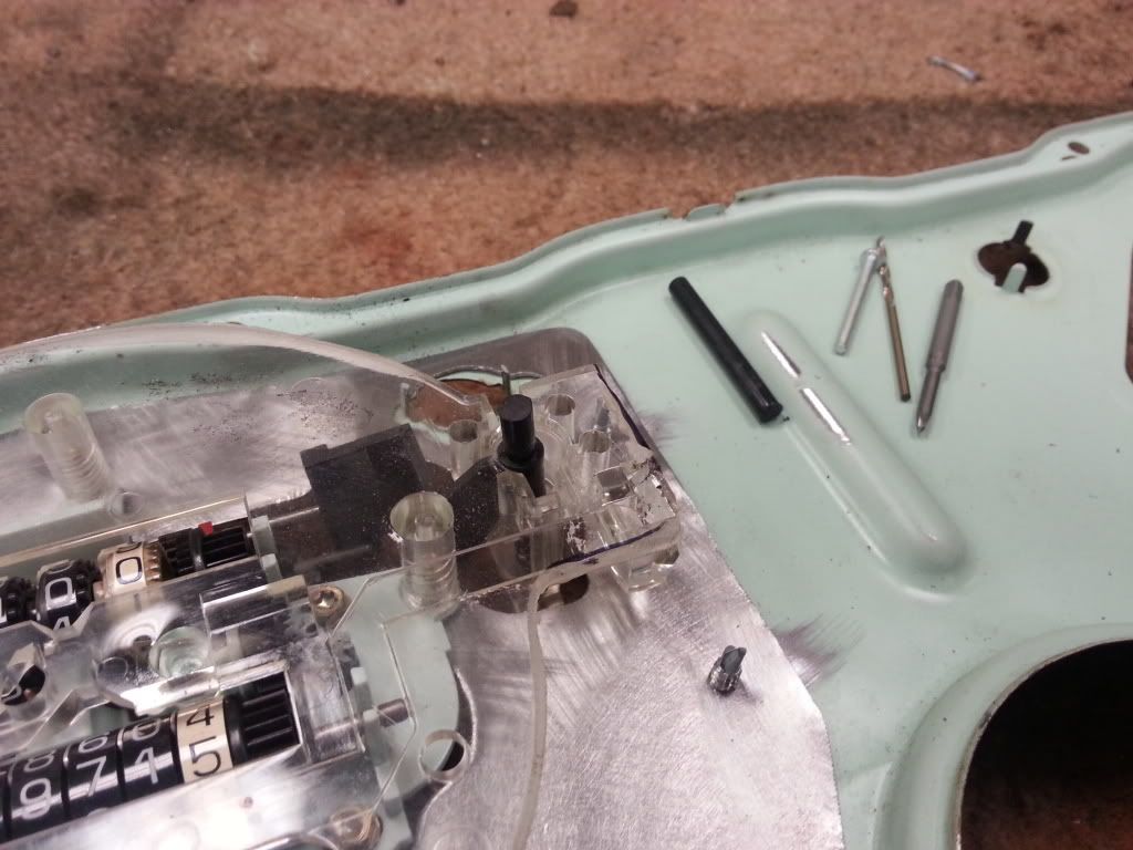 Drilled the hole in the end about 3/8" deep. I used a drill, but you could also put the bit in an X-Acto knife. Drilling plastic is really pretty easy, just make sure it's centered the best you can. 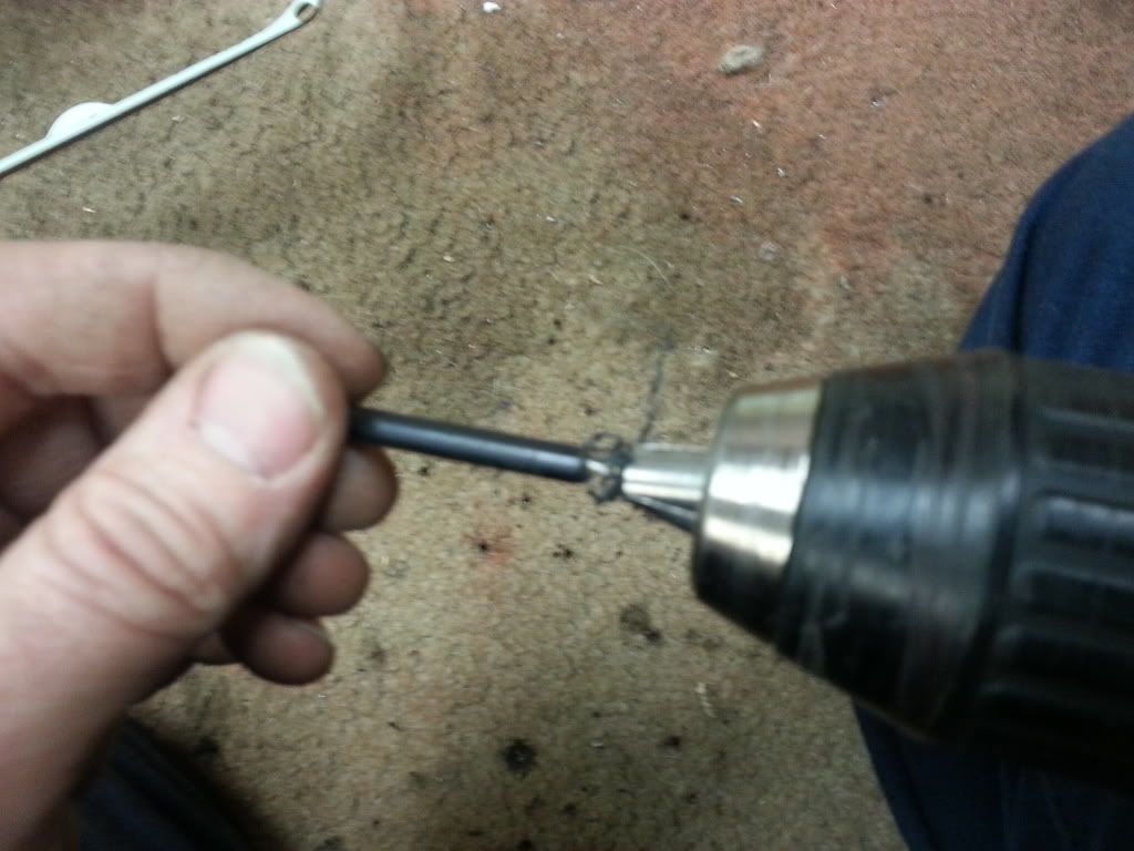 This is what it looks like drilled. 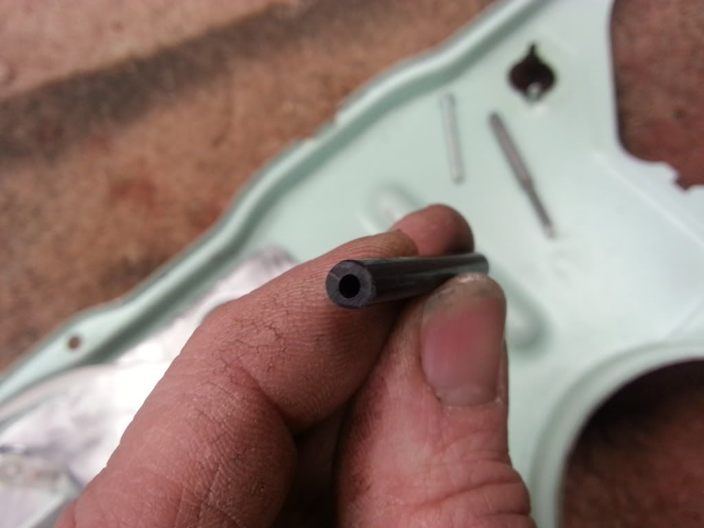 Then I put the tap in a pair of Vice Grips and tapped the hole. 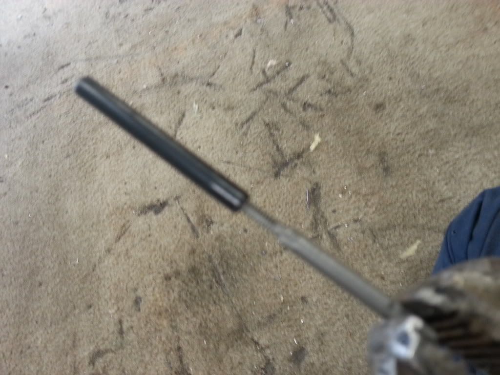 Then the screw will screw into it. 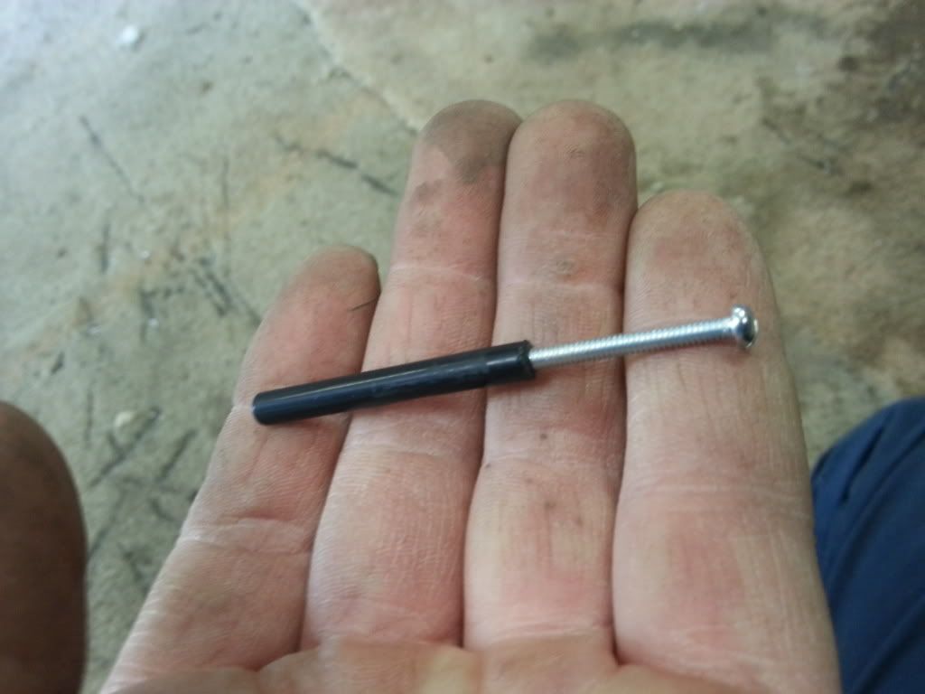 Drill and tap the other end, cut the head of the screw off and thread each end in. 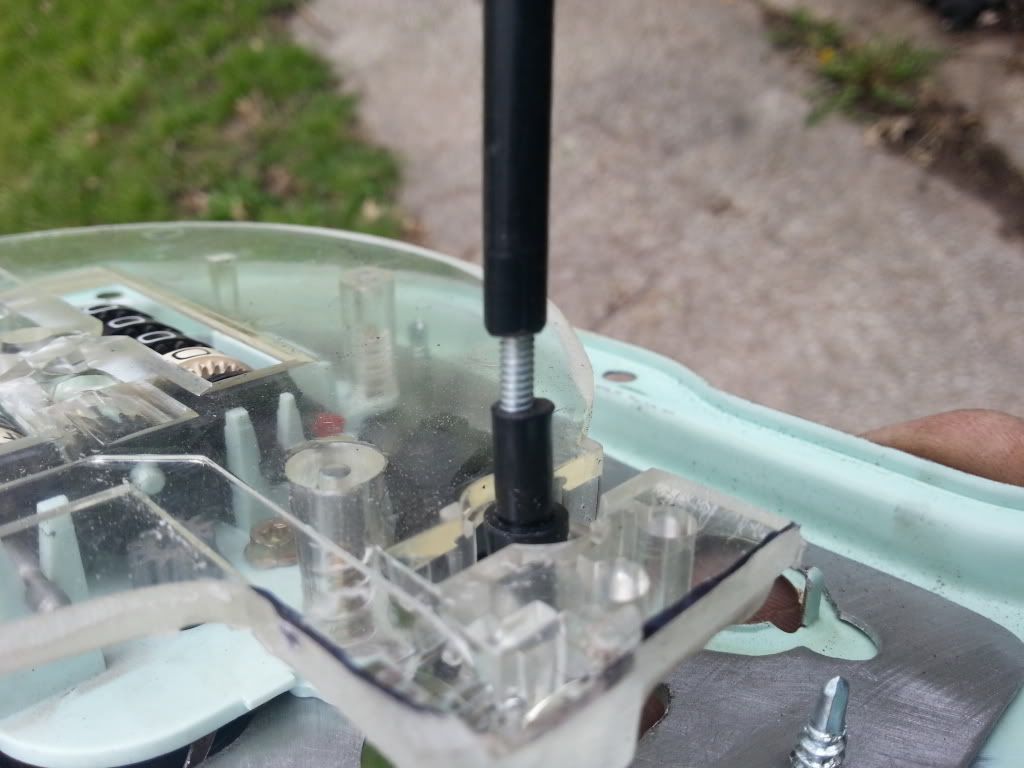 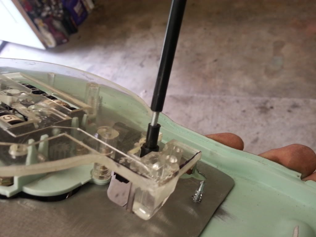 Later, after I've adjusted it to the length I want, I'll put some glue in them so it won't thread out, but odds are it wouldn't move anyway. You can also see that I didn't get the bottom part exactly centered, it's not a big deal, since you can just thread it in or out a bit to get it where you want it.
__________________
My '72 short bed build. http://www.ls1tech.com/forums/conver...6-0-4l80e.html 5.3 swap into my RUSTY '71 C10 http://ls1tech.com/forums/conversion...71-c-10-a.html |
|
|

|
|
|
#153 |
|
Registered User
Join Date: Dec 2009
Location: Independence Mo
Posts: 4,118
|
Re: 67-72 Electric speedo
Next is the needle. You'll need both the S-10 and your original needles. Start by bending the four tabs up on your original needle and remove the mounting part.
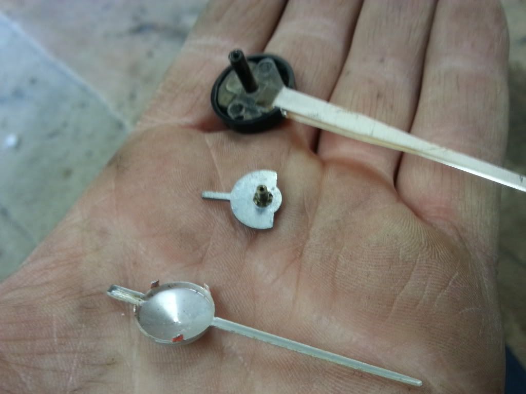 Then cut the black part off the S-10 needle, and trim it up so it will fit in the original needle. 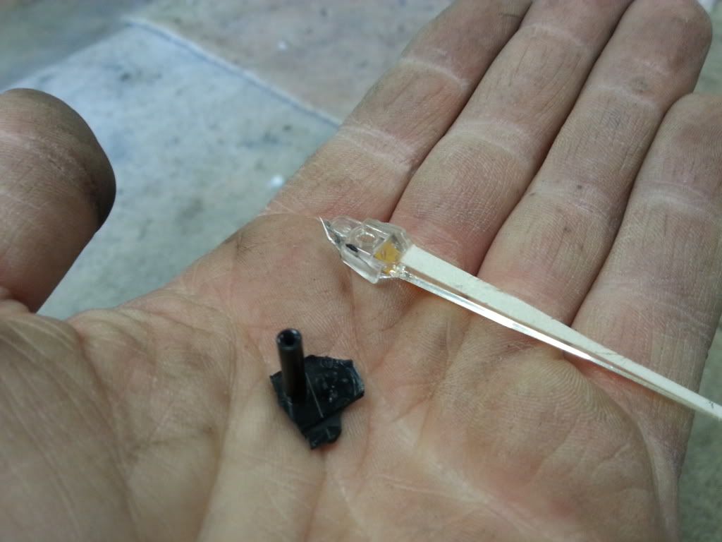 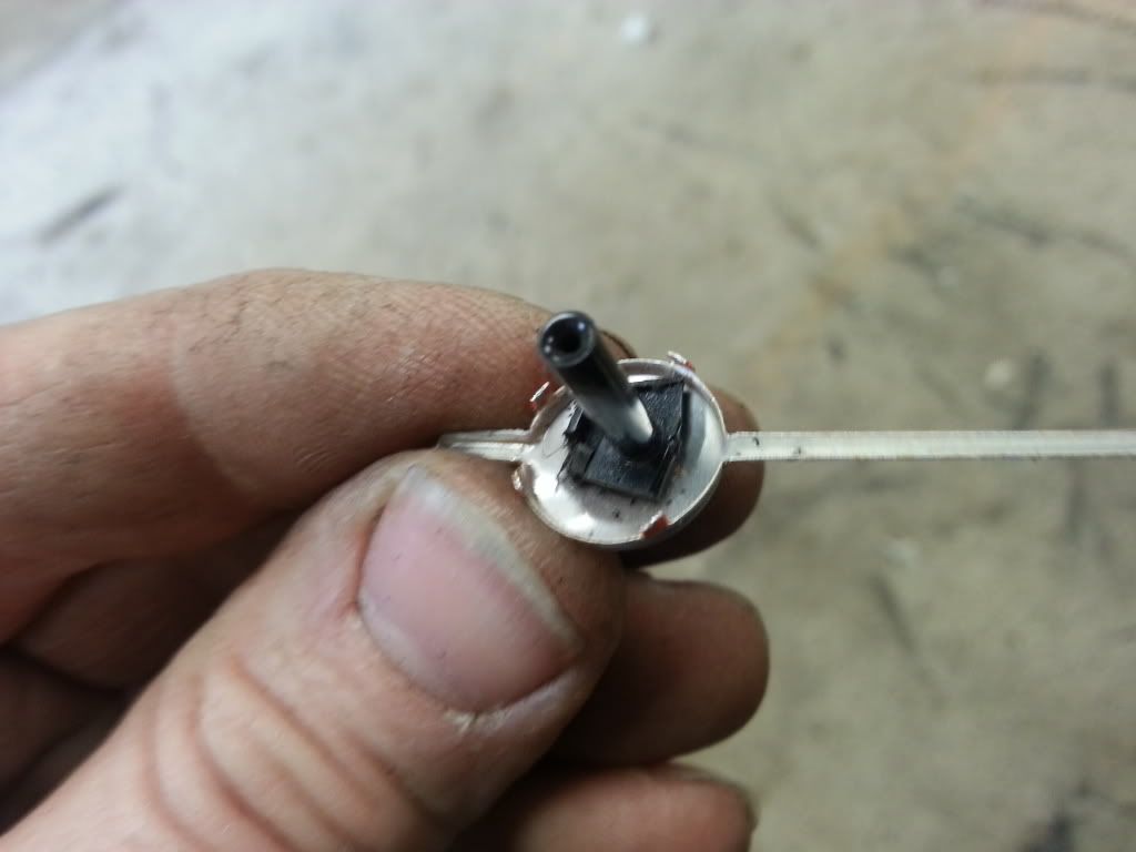 Then you'll need to epoxy the black part in the original needle. I used body filler because it sets up quick, and I had some. Mixed some up and put a little in the needle, then put the black part in it. 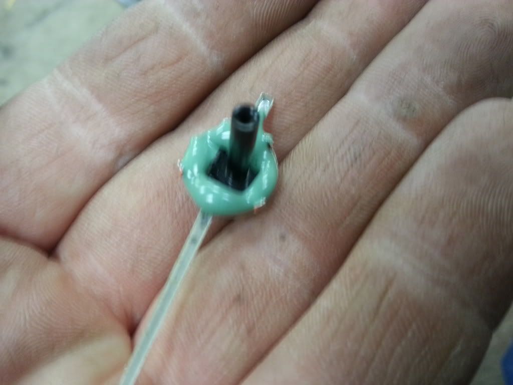 Then put a little more on it to cover it the rest of the way up. Make sure it's centered and straight up, you don't want it leaning at all. 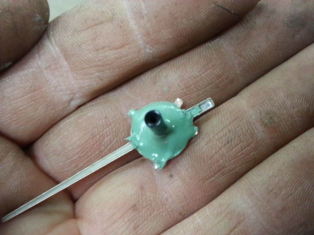 Then when it started to set up, but before it was completely hardened, I took a razor blade and trimmed it flat. 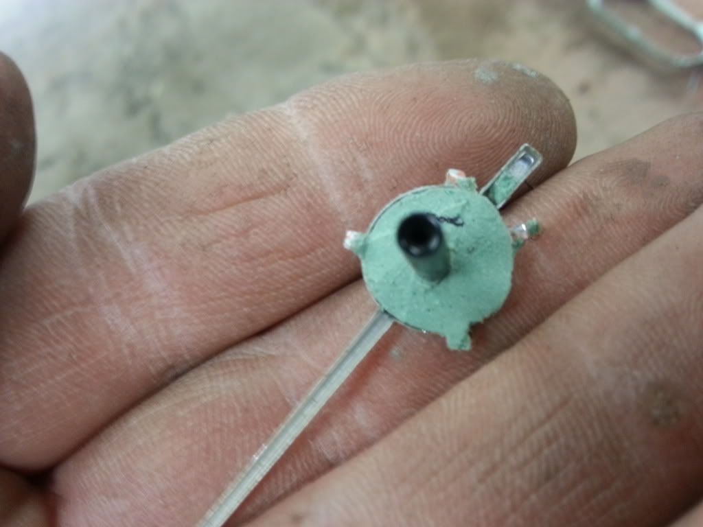 Then it fell out! LOL! No problem though, a little super glue and it was good to go. I also bent the tabs back over. 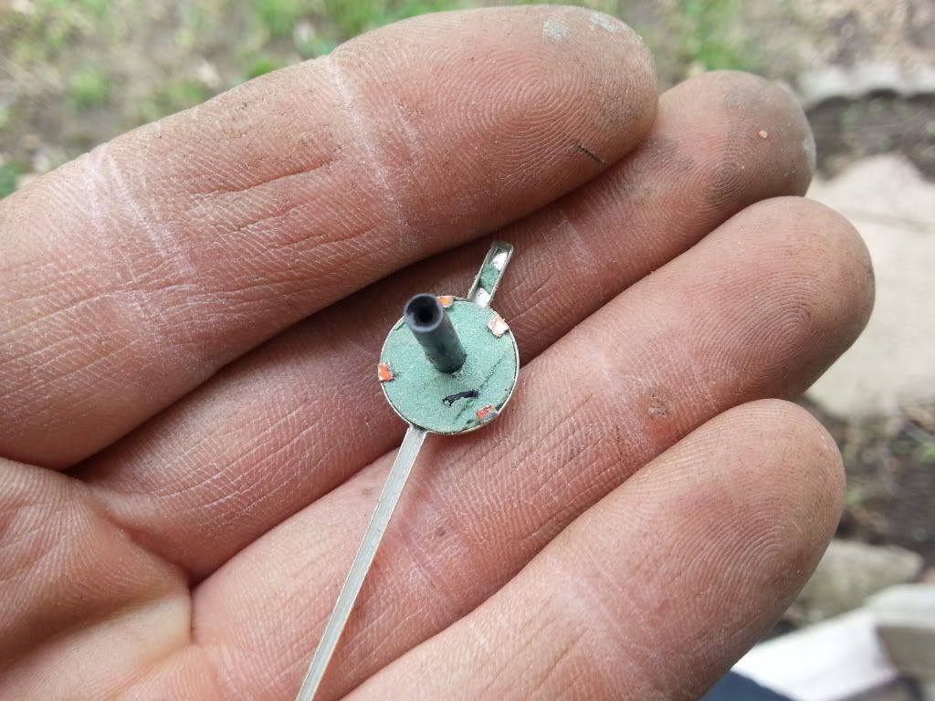 Now you'll find that it's a little too long, and the needle is too far off the face. Pull it back off and trim it down a bit. I did it a little at a time with a razor blade. Don't do alot at once, since if you cut it too short, you'll have to start over. 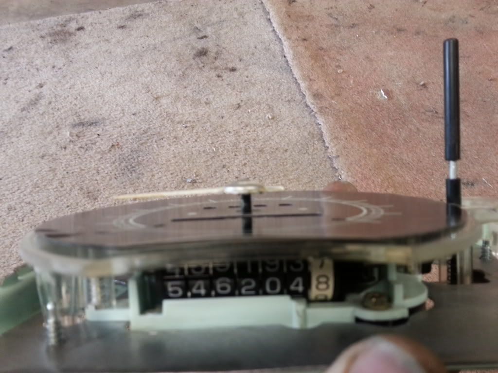 This is a little better. 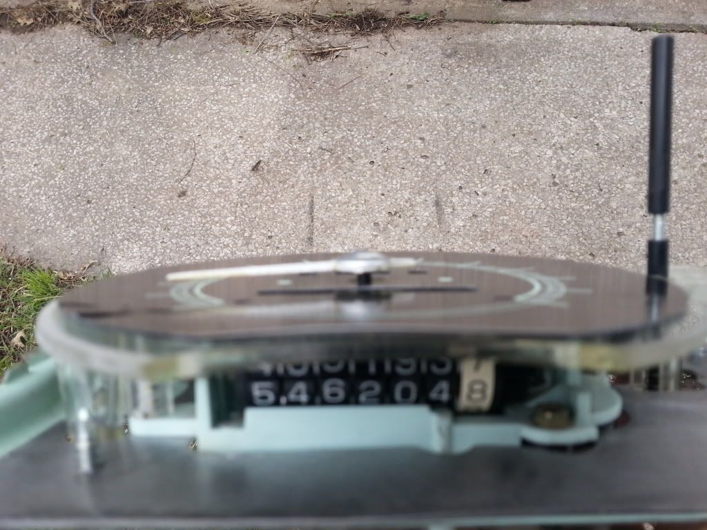 Now you can put the needle on, and make sure everythings lining up. If it's right, through the entire sweep, the needle will be right at the edge of the line on the speedo face. 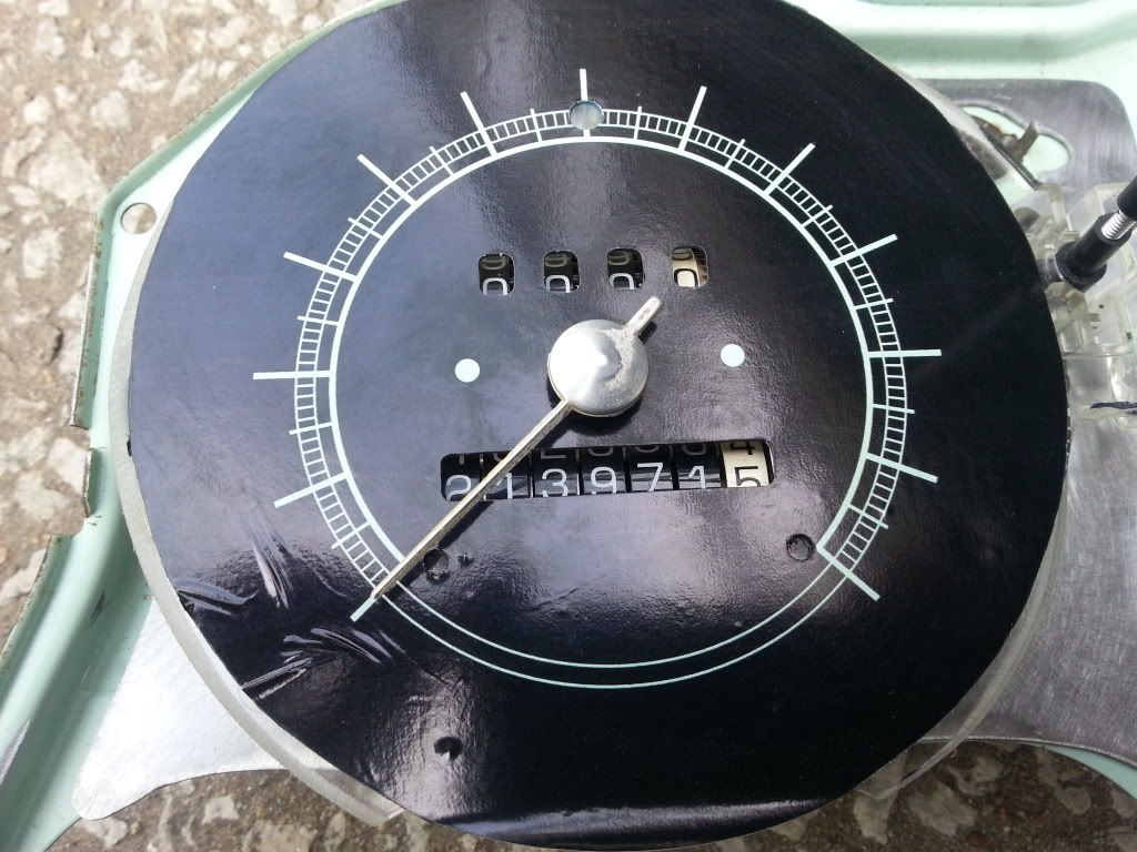 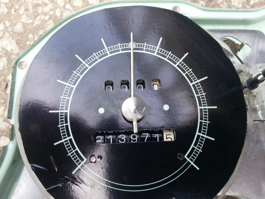 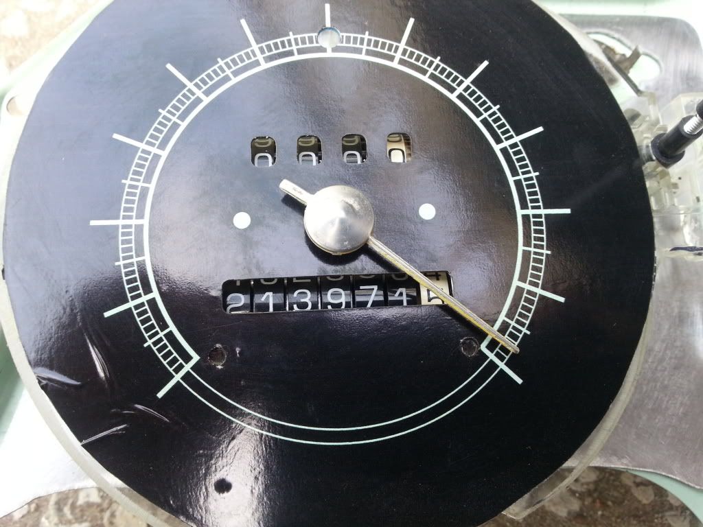 Should look like this. At this point it's just down to wiring. I use sockets for the lights from the junk yard. They are the same sockets that 67-72 trucks have on the heater controls, and use the same bulbs. they ground through the base, so you only need to run the power wires to them. 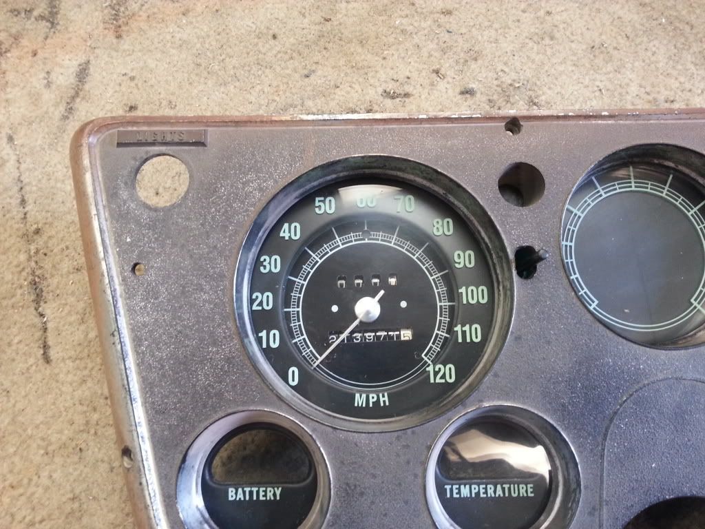 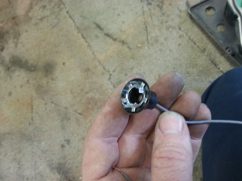 As for the rest of the wiring, use your old printed circuit as a guide, it will show you what wires on the gauges need power, and which ones go to the senders. I also usually go to the junk yard and get a connector to wire into it so that you can un plug the whole cluster to remove it. If anyone has any questions on wiring just ask and I'll get back with you.
__________________
My '72 short bed build. http://www.ls1tech.com/forums/conver...6-0-4l80e.html 5.3 swap into my RUSTY '71 C10 http://ls1tech.com/forums/conversion...71-c-10-a.html |
|
|

|
|
|
#154 |
|
Registered User
Join Date: Dec 2009
Location: Independence Mo
Posts: 4,118
|
Re: 67-72 Electric speedo
I forgot about the high beam indicator, but there's a pic on page 1 of this thread. It's a 12v LED I bought at Radio Shack. it has a small nut that threads on it so you can bolt it in a hole. I made a bracket that bolts to one of the screws that holds the speedo part in. I also ended up putting a piece of window tint under the face, between it and the clear plastic part, to keep it from appearing to glow when the dash lights are on. The dash lights will light up the clear and the indicator will be white. putting the window tint darkens it so you don't see it, but it's not so dark that the LED doesn't show through.
__________________
My '72 short bed build. http://www.ls1tech.com/forums/conver...6-0-4l80e.html 5.3 swap into my RUSTY '71 C10 http://ls1tech.com/forums/conversion...71-c-10-a.html |
|
|

|
|
|
#155 |
|
Registered User
Join Date: Dec 2009
Location: Independence Mo
Posts: 4,118
|
Re: 67-72 Electric speedo
I only put the 2 screws back in the face for cosmetic reasons. I think it looks better, and there are two white dots on the face where they go. I just drilled the holes small enough so that the screws screw into the face, but are not actually holding anything.
__________________
My '72 short bed build. http://www.ls1tech.com/forums/conver...6-0-4l80e.html 5.3 swap into my RUSTY '71 C10 http://ls1tech.com/forums/conversion...71-c-10-a.html |
|
|

|
|
|
#156 |
|
Registered User
Join Date: Jan 2010
Location: Grimsby, Ontario
Posts: 205
|
Re: 67-72 Electric speedo
I'm interested in a kit if there is any available? Could always use the metal plate as well if they are being made yet.
|
|
|

|
|
|
#157 | |
|
Registered User
Join Date: Apr 2011
Location: Mustang, Oklahoma
Posts: 2,806
|
Re: 67-72 Electric speedo
Quote:
 Q: does the needle have to sit up higher that the stock needle? Just wondering if I couldnt just bore out the stock needle hole to fit or would it be too short? I am almost done with the mounting plate but have a bit to go on the rear cover box. Those pesky light bulbs make it difficult. I may make another one and just use LEDs to backlight it like the one you used for the high beam indicator. I think that would give me a bit more wiggle room for the rear cover box. Here are some pics of the almost finished plate and my progress.
__________________
Dan <---(my name) 67 SWB C10 project "GEORGIA"-59 Brookwood 2dr wag...Next project-03 Tahoe 4x4 5.3 family ride-07 Hondur Accord, commuter car |
|
|
|

|
|
|
#158 |
|
Registered User
Join Date: Apr 2011
Location: Mustang, Oklahoma
Posts: 2,806
|
Re: 67-72 Electric speedo
A few more pics

__________________
Dan <---(my name) 67 SWB C10 project "GEORGIA"-59 Brookwood 2dr wag...Next project-03 Tahoe 4x4 5.3 family ride-07 Hondur Accord, commuter car |
|
|

|
|
|
#159 |
|
Registered User
Join Date: Dec 2010
Location: NC
Posts: 666
|
Re: 67-72 Electric speedo
You sir have great skill. Very clean work. You and ls1nova71 are both geniuses. Cash in hand. Waiting on any kit you offer. Thanks to both of you guys for sharing all of this and not keeping it your own secret. This is what makes the site great
 Posted via Mobile Device |
|
|

|
|
|
#160 | |
|
Registered User
Join Date: Dec 2009
Location: Independence Mo
Posts: 4,118
|
Re: 67-72 Electric speedo
Quote:
 ) I guess if you have a drill bit that small you could drill it out to fit, but damn, that would be a really small drill bit! ) I guess if you have a drill bit that small you could drill it out to fit, but damn, that would be a really small drill bit!
__________________
My '72 short bed build. http://www.ls1tech.com/forums/conver...6-0-4l80e.html 5.3 swap into my RUSTY '71 C10 http://ls1tech.com/forums/conversion...71-c-10-a.html |
|
|
|

|
|
|
#161 |
|
Registered User
Join Date: Dec 2009
Location: Independence Mo
Posts: 4,118
|
Re: 67-72 Electric speedo
Don't have any more at this time, but may in the future. I'll let you know when the time comes.
__________________
My '72 short bed build. http://www.ls1tech.com/forums/conver...6-0-4l80e.html 5.3 swap into my RUSTY '71 C10 http://ls1tech.com/forums/conversion...71-c-10-a.html |
|
|

|
|
|
#162 |
|
Registered User
Join Date: Dec 2010
Location: NC
Posts: 666
|
Re: 67-72 Electric speedo
Just thinking (dangerous I know) if you devided your gear ratio in the PCM by 1.2 could you keep the original face and the 0-100 on the lens? I.e. if you had a 3.07 you would enter 2.56 in the PCM. You could also modify tire size in the same manner. Would this work?
Posted via Mobile Device |
|
|

|
|
|
#163 | |
|
Registered User
Join Date: Dec 2009
Location: Independence Mo
Posts: 4,118
|
Re: 67-72 Electric speedo
Quote:
Posted via Mobile Device
__________________
My '72 short bed build. http://www.ls1tech.com/forums/conver...6-0-4l80e.html 5.3 swap into my RUSTY '71 C10 http://ls1tech.com/forums/conversion...71-c-10-a.html |
|
|
|

|
|
|
#164 | |
|
Registered User
Join Date: Dec 2010
Location: NC
Posts: 666
|
Re: 67-72 Electric speedo
Quote:
 Posted via Mobile Device |
|
|
|

|
|
|
#165 |
|
Registered User
Join Date: Jan 2010
Location: Grimsby, Ontario
Posts: 205
|
Re: 67-72 Electric speedo
Thanks. I'll try and wait patiently until then. Great job done by the both of you.
Posted via Mobile Device |
|
|

|
|
|
#166 |
|
Registered User
Join Date: Apr 2011
Location: Klein Texas
Posts: 3,852
|
Re: 67-72 Electric speedo
Subscribed
You can put me down for a print if you make another run. For the others, perhaps an old school VSS buffer from a carbed GM would drive the speedo?
__________________
My Classics: '72 K20 Suburban + '65 Dodge Town Wagon '72 Corvette Roadster +'67 Corvette Roadster '73 Z-28 Camaro '63 Ford SWB Uni Pickup '50 Ford Coupe |
|
|

|
|
|
#167 |
|
Registered User
Join Date: Jan 2010
Location: Grimsby, Ontario
Posts: 205
|
Re: 67-72 Electric speedo
Eric,
Can I ask you if its possible to make the speedo in KPH? Maybe you could put me in touch with your designer to get it done. Or a copy of the program to get it altered here. I bought a S-10 cluster here in Canada and its in Kilometers. I thought it would be cool to run it that way. Otherwise I'd end up with KM odometer and Miles on the speedo. Thanks Jim |
|
|

|
|
|
#168 |
|
Registered User
Join Date: Jan 2010
Location: Grimsby, Ontario
Posts: 205
|
Re: 67-72 Electric speedo
Eric,
Can I ask you if its possible to make the speedo in KPH? the O would be the same and the 50 mph is the same as 80kph and 100 mph is 160 kph. Maybe you could put me in touch with your designer to get it done. Or a copy of the program to get it altered here. I bought a S-10 cluster here in Canada and its in Kilometers. I thought it would be cool to run it that way. Otherwise I'd end up with KM odometer and Miles on the speedo. Thanks Jim |
|
|

|
|
|
#169 |
|
Registered User
Join Date: Sep 2009
Location: Weare,NH
Posts: 1,592
|
Re: 67-72 Electric speedo
GM DRAC/VSSB Calibration
If you are carbed, this is what you need to drive an electric speedo. They are easy to find in 92-95 Chevy/GMC full size trucks, its a white box mounted under the ECM. Make sure you take the pigtail as well. Easy to wire it too. Just de-pin wires you won't be using and braid together the VSS sensor wires to prevent interference. Connect 12V+ switched thru a 2A fuse, ground, and the C15 VSS output to the speedometer input. Calibrate the box using the method above, and done. Way cheaper ($5 if the junkyard even charges you) and guaranteed to work correctly vs the universal Dakota Digital method for $89. |
|
|

|
|
|
#170 |
|
Registered User
Join Date: Apr 2011
Location: Mustang, Oklahoma
Posts: 2,806
|
Re: 67-72 Electric speedo
Working on a redesigned box and have a few Questions.
 1. First the box dilemma. I designed this with flanges that tuck inside to be spot welded so it would be easier than welding seams with a mig. Works okay but the jaws on our spot welder head butt the opposite edge in a couple places, arrgh. Not terrible but forming this was a bear! Might be a better idea to use small sheet metal screws? or rivets? or just remove the tucked in flanges and seam weld? Opinions?? when I have the flanges tuck in there is a small gap in the corners, do you think this needs to be water tight or just a dust cover? 2. The flippin crappin lights  I angled both upper corners at 45* one side to stay inside the edge of the tin the other to clear the light (instead of rounding the corner like the template) but my box and the one I made from the paper template interfere with the odo reset (barely) so I have to make it just a bit wider. So why not enclose the inboard light under the box too? (pic 4) I angled both upper corners at 45* one side to stay inside the edge of the tin the other to clear the light (instead of rounding the corner like the template) but my box and the one I made from the paper template interfere with the odo reset (barely) so I have to make it just a bit wider. So why not enclose the inboard light under the box too? (pic 4)3. along with Q 2, if I enclose the light will It cause interference with the Tach? I don't have a tach, and does a factory tach even work with an LS? I keep trying to make these lightbulbs work but seriously think I will have to go with small LED lights to get something I am really happy with because they are just in the way soooo much. My flanges are too wide and screw holes are too big so nevermind the slight overhang. Will try some more improvements tomorrow.
__________________
Dan <---(my name) 67 SWB C10 project "GEORGIA"-59 Brookwood 2dr wag...Next project-03 Tahoe 4x4 5.3 family ride-07 Hondur Accord, commuter car |
|
|

|
|
|
#171 |
|
Registered User
Join Date: Sep 2009
Location: Weare,NH
Posts: 1,592
|
Re: 67-72 Electric speedo
Factory tach will work with an LS engine, you just have to re-program the PCM output to 6 or 8 cylinder pulse; depending on what your tach is calibrated for.
|
|
|

|
|
|
#172 | |
|
Registered User
Join Date: Dec 2010
Location: NC
Posts: 666
|
Re: 67-72 Electric speedo
Quote:
 ) I would say forego the spot and seam welding and go with sheet metal screws referencing factory holes if possible. I would think it only needs to be a dust cover not water tight. I for one would prefer to not even use the trip odo so the reset interference is of no consequence to me. I would suggest covering the offending light bulb if it can be done without interfering with a factory tach. ) I would say forego the spot and seam welding and go with sheet metal screws referencing factory holes if possible. I would think it only needs to be a dust cover not water tight. I for one would prefer to not even use the trip odo so the reset interference is of no consequence to me. I would suggest covering the offending light bulb if it can be done without interfering with a factory tach. Keep plugging away man! Many thanks! Posted via Mobile Device |
|
|
|

|
|
|
#173 | |
|
Registered User
Join Date: Dec 2009
Location: Independence Mo
Posts: 4,118
|
Re: 67-72 Electric speedo
Quote:
 2. You could enclose the turn signal indicator light if you want to, it's no different than enclosing the two dash lights, but I think the box would have to be bigger across the top. 3. THe factory tach will work with the engine, but you need to set the tach resolution from 6 to 3 in the tune, this will double the output since LS engines use a 4 cylinder output from the factory. As for the tach actually fitting, it's close! But it will fit, although if you enclose the turnsignal light, I would get a tach and make sure it doesn't hang over where the tach needs to be. Here are the pics of my first one that I put a tach in for reference.
__________________
My '72 short bed build. http://www.ls1tech.com/forums/conver...6-0-4l80e.html 5.3 swap into my RUSTY '71 C10 http://ls1tech.com/forums/conversion...71-c-10-a.html |
|
|
|

|
|
|
#174 | ||
|
Registered User
Join Date: Dec 2009
Location: Independence Mo
Posts: 4,118
|
Re: 67-72 Electric speedo
Quote:
Quote:
__________________
My '72 short bed build. http://www.ls1tech.com/forums/conver...6-0-4l80e.html 5.3 swap into my RUSTY '71 C10 http://ls1tech.com/forums/conversion...71-c-10-a.html |
||
|
|

|
|
|
#175 |
|
Registered User
Join Date: Jan 2010
Location: Grimsby, Ontario
Posts: 205
|
Re: 67-72 Electric speedo
Eric,
I wouldn't need to have 19 different lines ordinarily in KPH they go every 20 kph intervals so I would just use 0, 20, 40, 60, 80, 100, 120, 140, 160, 180, 200 even for a total of 10 max. With the 0 the same and 80 kph at the 50mph 160 at 100mph as those are direct conversion and evenly space the rest out to match. Could let it end at 180 kph if that made it easier. Either way when you get another order going I'll get a set and if need be go and see if I can use that one as a template for a KPH one. Then go to a graphic designer from there. I guess I should just return the KPH one here and get a MPH from the states to make my life easier just thought it would be cool to have it kilometers. |
|
|

|
 |
| Bookmarks |
| Thread Tools | |
| Display Modes | |
|
|