
 |
Register or Log In To remove these advertisements. |
|
|
|
|||||||
 |
|
|
Thread Tools | Display Modes |
|
|
#1 |
|
Registered User
Join Date: Nov 2007
Location: Central Minnesota
Posts: 631
|
Introduction: In the following article, we'll outline how to install a remote start unit in your 88-98 Truck/SUV. Year to year the install may vary slightly due to different features and wire colors that your truck is equipped with. This particular install is on a 1994 GMC Sierra SLE K2500 with factory power door locks. This truck does not have Factory Keyless Entry. Each Remote Start Unit out there will also vary in the manner that it is installed as it may have other features or less features, different wire colors, more/less wires, etc. This article will outline where each wire is on the truck and what it does, so you have a good understanding of what is all involved. On the 95-98 Model trucks, you may need additional parts such as a bypass module, and you may need to connect a few more wires then are described in this article.
NOTE: This truck had a remote start unit previously installed by the previous owner, so you may notice extra wires that are not noted in the following article. Disregard unless noted otherwise. That unit was completely removed immeadiately before beginning the install on the new remote start unit. *****DISCLAMER****** This article is a guide to installing a remote start unit, and outlines the way we installed THIS remote start unit on THIS particular 1994 GMC Sierra. Please realize that every vehicle can be different and every remote start unit can be different. Please follow the install manual for your particular unit, and follow proper safety procedures. Such as NEVER run your vehicle in a closed garage, etc etc. ------------------------------ Required Tools: -Phillips Screwdriver -Torx Head Bit Set -3/16" or 7mm Socket -Wire Stripper -Terminal Crimper -Wire Cutter/Side Cutter -Cordless Trouble Light (VERY HELPFUL) -Folding Sheetrock Knife or Razor Blade -Soldering Iron* (*Optional but strongly recommended) -Solder* (*Optional but strongly recommended) -Flux* (*Optional but strongly recommended) -Drill Bit -Digital or Analog Multi-Meter (DO NOT USE TEST LIGHT UNDER DASH) -Heat Shrink Tubing -Various Connectors -Zip Ties ----------------------------- Other Misc. Items Needed: -Hood Pin Switch (If Not Included with kit) -Relay(s) (2-3) (If required with your remote start unit) -Electrical Tape -Rubber Grommet(s) ------------------------------- Difficulty Level: 3/5 for the average person with a basic automotive knowledge level. (If you have a strong understanding of automotive electrical, then it will be a very easy straight forward install.) Install Time: 2.5-8 Hours. (Again, install time varies on your abilities. This particular install took me a little under 3.5 hours, taking my time and making notes and taking pictures along the way) --------------------------------- Alright Lets get started then! First I recommend that you sit down and read the instruction manual front to back, and make a game plan on the install (eg. where your going to start). Also I would recommend that you locate a wiring diagram for your particular year truck. This will prove to be very helpful, and will help reduce your install time. Now once your ready to begin, I recommend you set up a bench beside your truck and lay out the remote start kit and everything that you will need for the install. This allows your tools to be an arms reach away when your under the dash. And your not getting up and walking to your tool box every 5 minutes. Here's a few of the tools that you will need, there are several tools that are not in the picture; but here's a few of the basics that you'll need: 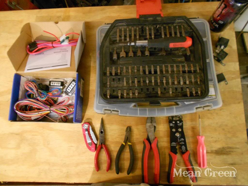 Here is the remote start unit that we installed, it is a Crimestopper unit and I highly recommend it! It features keyless entry, as well as the remote start function, and has over 26 different programmable options: 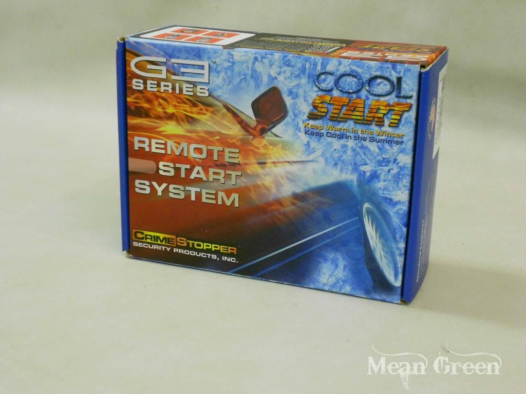 Here is what is all included with this particular unit:  -------------------------------- Now its time to get your hands dirty, so to speak. I recommend that you roll down a window before you begin to prevent accidentally locking yourself out during the install. First your going to want to remove the knee bolster panel, on the 88-94 trucks this is accomplished by removing two Phillips head screws that are located on the bottom edge of the panel. After this is removed you will likely want to remove the gauge cluster trim bezel as well. This bezel is held into place by (4) Torx head screws, there is one in each corner of the bezel. The 2 pictures below will allow you to see the screws. After you have the screws out, shift the truck into low gear (Applies to Automatic trucks only) so that you can slip the bezel past the shift lever. Now remove the connectors off the back of the headlight switch, there will be 2 connectors on the headlight switch itself. And there will be one for the cargo light switch as well, if equipped: 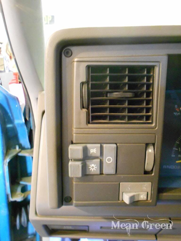 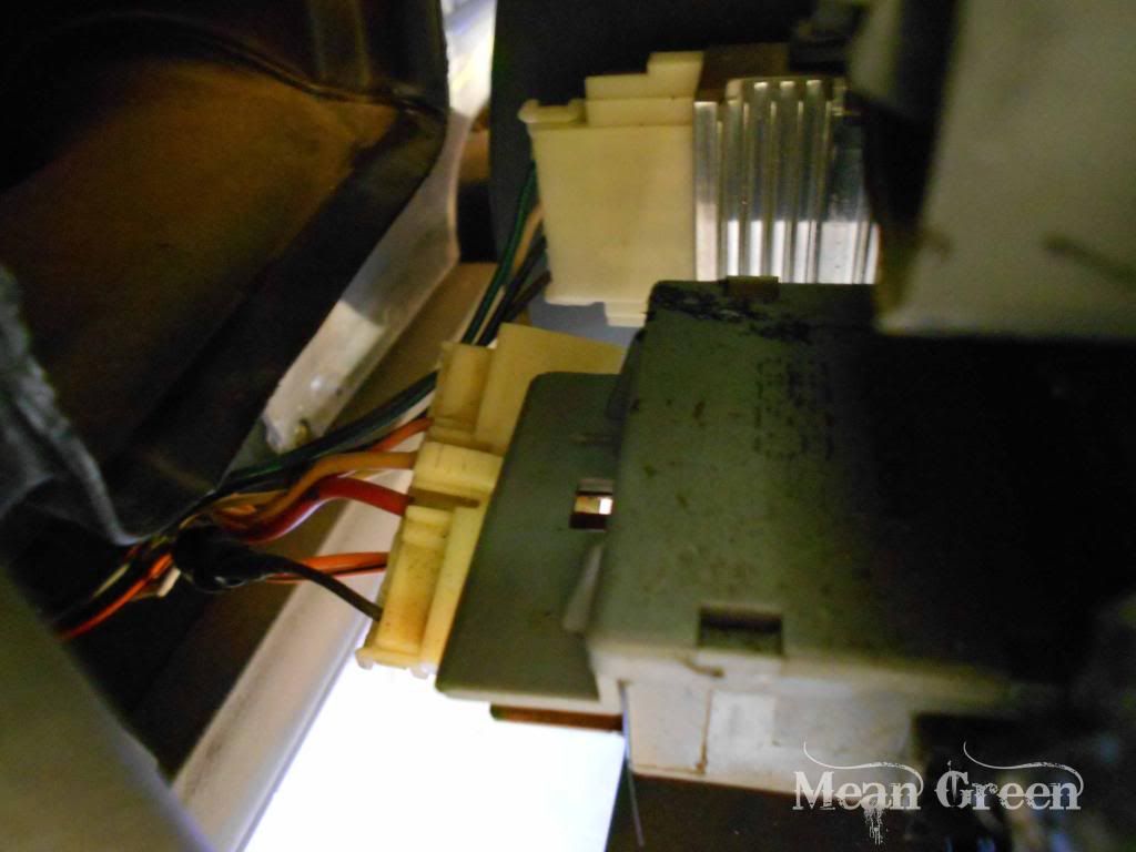 -------------------------- After all of that is out of the way, I opted to mount the remote start "brain" unit itself first. By doing this, I could cut all the wires to length when installing them and would also allow for a cleaner install. You don't have to do this first, I simply thought it best. I mounted the remote start unit to the dash brace above the junction block on the driver side firewall. I mounted it utilizing a #8 1/2" self tapping screw. 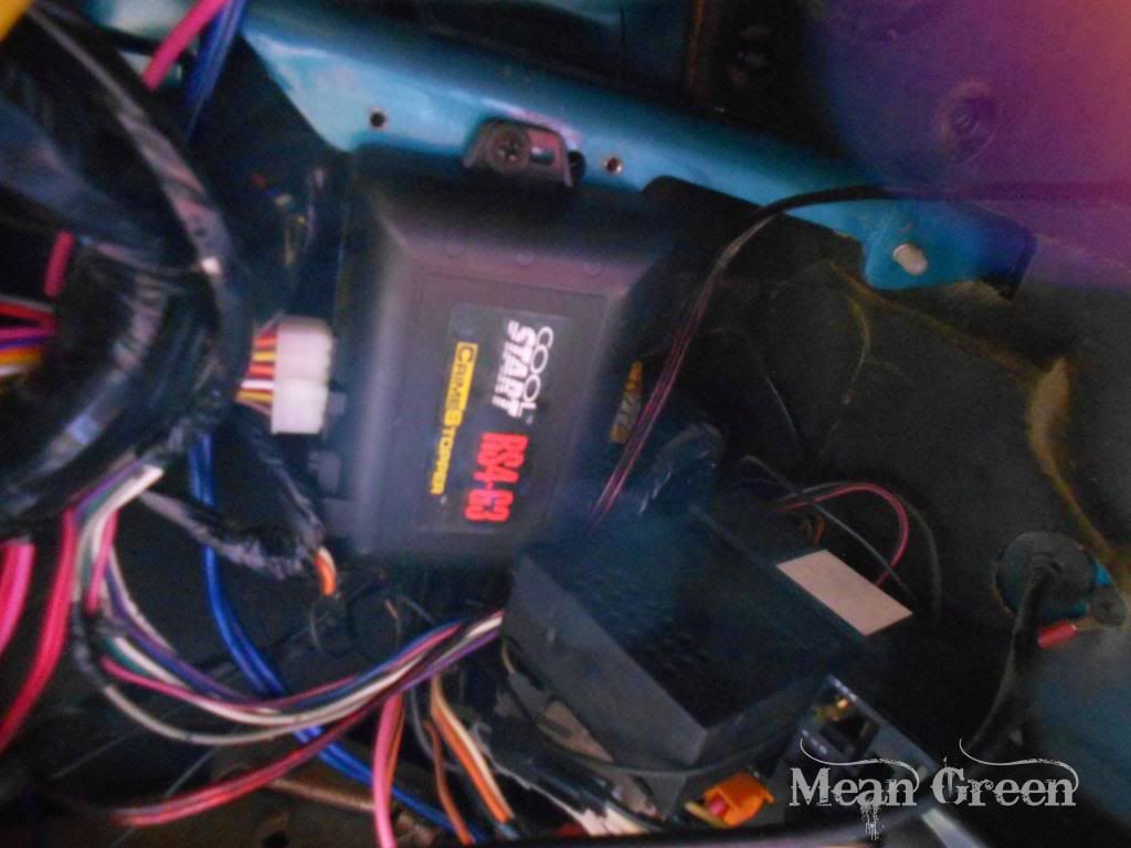 Now I plugged in the first harness that I was going to install onto the truck. In this particular case it was the "Low current, 12 Pin" harness. This harness consists of the horn honk output, ground, anti-grind, dome light supervision, parking light flash output, hood pin switch input, brake switch input, tach input etc. I now routed the harness above the factory harness and began hooking up each wire to the appropriate place. Below I'll list where/color each wire was on my 94', this may vary on your particular year truck but it should be located in the same or similar location on all GMT400's. From Remote Start : Truck Wire Location/Color: -------------------------------------------------- Horn Honk Output : Black Wire on steering column harness (By grounding this wire, it should honk the horn) Main System Ground : To a bare metal chassis ground, sand/wire wheel down the grounding point to ensure a good ground (Pic #1) Dome Light Illumination White wire on the backside of the headlight switch, this is a GROUND (Pic #2) 12V Input : Constant 12V+ Terminal on the interior junction block. Use your DMM to locate a terminal that is always hot Parking Light Output : Brown wire on backside of headlight switch, this is 12V+ when the parking lights are on. (Pic #2) Hood Pin Switch Output: This wire you are going to need to drill or utilize an existing hole in your firewall to run into the engine bay.(Pic #3) Bake Switch Input : White Wire coming off of brake light switch this wire will ONLY have 12V+ when the brake pedal is depressed. Tachometer Input : This wire will be located behind the glove box, at the vehicles ECM or "Computer". It will provide AC voltage, so set your DMM accordingly to locate it (Only while truck IS running) Picture #1 Showing the ground location I used. I used a #10 1/2" self tapping screw to secure the ground eyelet: 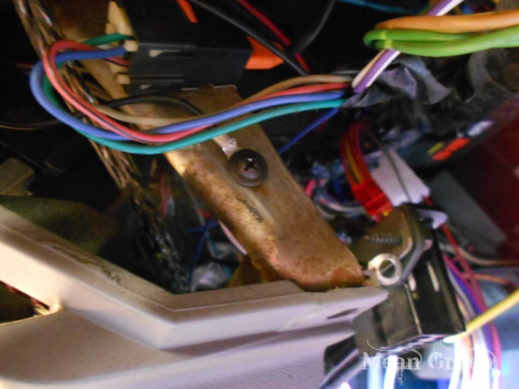 Picture #2 Showing the wires that I tapped into behind the headlight switch. This is the parking light and dome light wires: 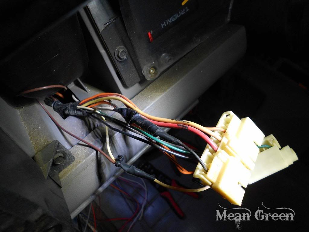 Picture #3 Showing the hole that I drilled in the firewall for the hood pin switch. BE SURE TO INSTALL GROMMET: 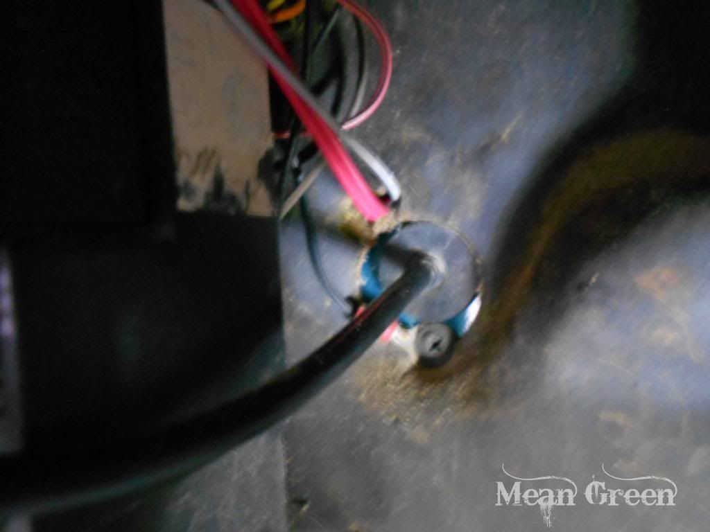 ------------------------------------------------- Now we are going to move on to wiring in your trucks power door locks, so that you can utilize the keyless entry feature! Please NOTE: If you have factory keyless entry, you have a few options here. You can either disconnect the factory keyless entry and use the new remote start's keyless entry option or integrate the factory key fob into the system. I did not have factory keyless entry, so this will be how to wire them in if you do not have factory keyless entry OR you decide to disconnect the factory keyless entry. First off your going to need to locate the power door lock wiring. I chose to tap into the the wires below the drivers side dash speaker, they are also ran through the kick panel (for the 95-98 guys that don't have dash speakers). To remove the speaker, simply release the two clips holding the grille onto the dash by using a flathead screw driver to release them. Now the speaker is held in to place with (4) 7mm screws. Remove the screws and set the speaker aside for now. You are looking for 2 wires in this harness, one wire is going to be Light Blue and one wire is Black/White. Your truck may have different color wires for the door locks, so consult your year specific wiring diagram for the proper wire colors. All GMT400 TWO door trucks utilize a REVERSE POLARITY door lock system, Tahoe's and crew cabs do not. This means that the lock motor solenoid is controlled by the switch in the door and not relays. Both of these wires rest a 0V GROUND, and raise to 12V+ when the switch is pressed to lock or unlock the doors. Once you locate the proper 2 wires you are going to CUT each wire in half. So you now have 4 wires to work with, I soldered a 12" wire lead on each and dropped it down to the foot well to connect it. You don't have to do this, it was just the easiest route for me. Be sure to heat shrink the connections and/or tape them with electrical tape. Below is how I wired in the relays required for the install. My particular remote start unit had a 3 pin plug to control the door locks; 2 grounds and 1 12V+ output. The door locks on the 2 door Chevy/GM trucks are Reverse Polarity. Here is the pin out for the relays: Relay #1 (Controls UNLOCK function) #85: Negative UNLOCK input from Remote Start Unit #86: Positive Output from remote start unit #87: Fused 12V+ CONSTANT #87A: Unlock input from master switch (Will be the unlock wire on the LEFT while looking at the wires you cut) #30: Unlock Output to passenger side (Will be the unlock wire on the RIGHT while looking at the wires you cut) Relay #2 (Controls LOCK function) #85: Negative LOCK input from Remote Start Unit #86: Positive Output from remote start unit (Splice into the same wire you used on terminal #86 on relay #1) #87 Fused 12V+ CONSTANT #87A: LOCK Input from master switch (Will be the LOCK wire on the LEFT side while looking at the wires you cut) #30: LOCK Output to passenger side (Will be the LOCK wire on the RIGHT side while looking at the wires you cut) Next mount the relays to a dash brace and make sure that wires are secured properly and such. MAKE SURE ALL CONNECTIONS ARE HEATSHRUNK and/or taped to ensure a good insulated connection. Below are pictures of the above procedure. Please excuse the messy taped connection in the first picture, this was done by the previous owner and I did not take a picture after I re-did the connection: 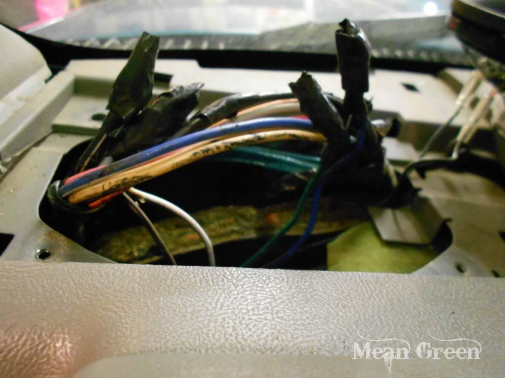 Relays wired in: 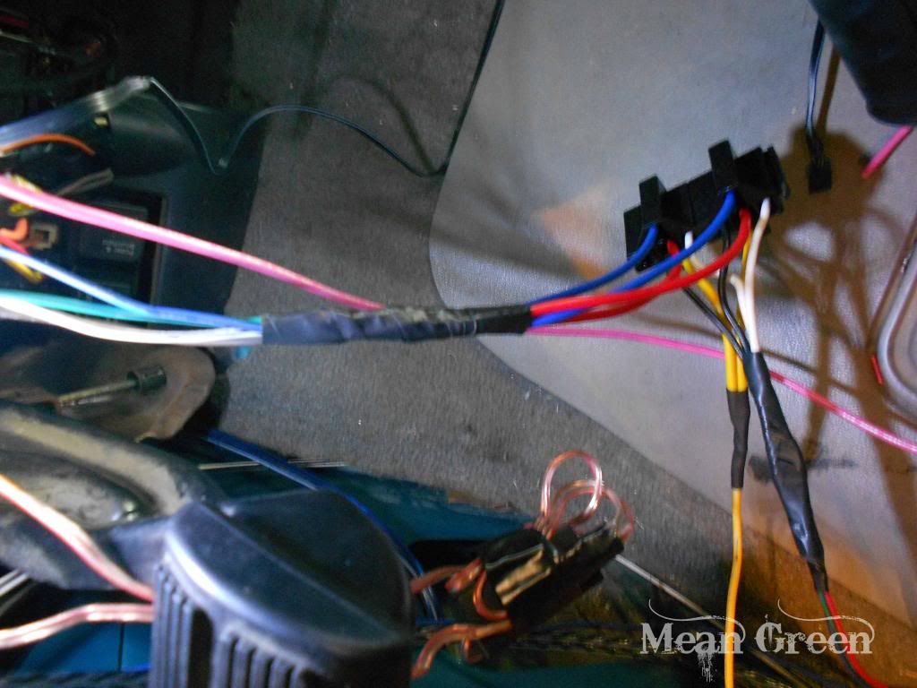 Relays securely mounted using 1/2" #10 Self Tapping Screws: 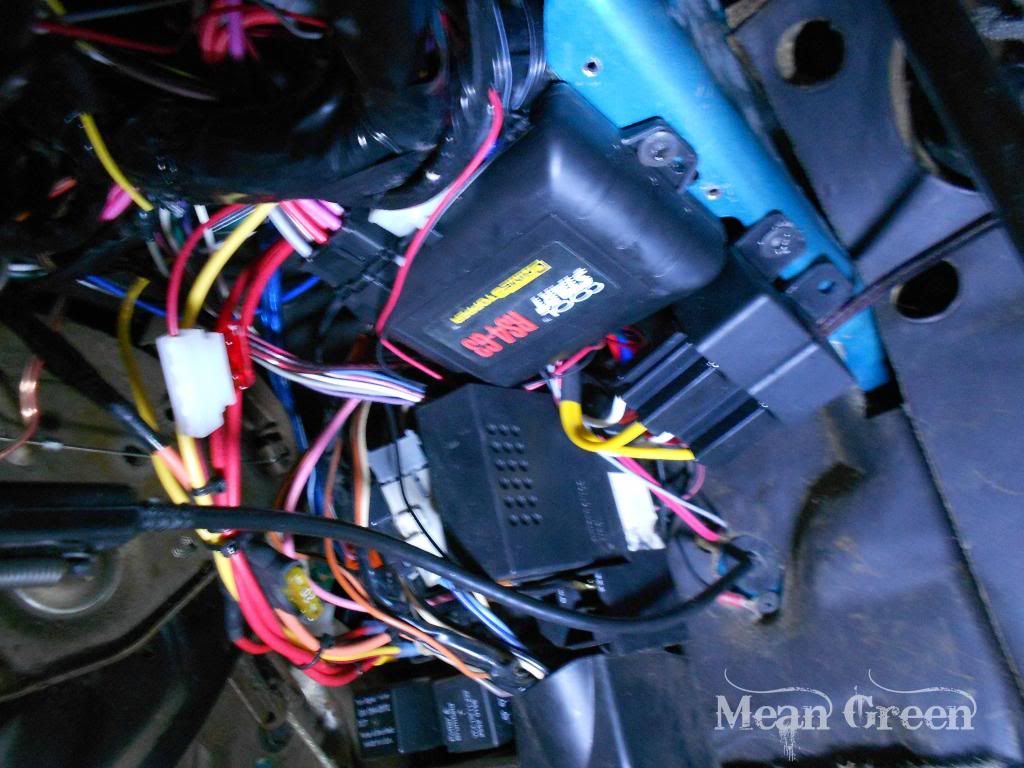 -------------------------------------------------------------------------------------- Now you are in the home stretch!! Your almost done with the major part of the install, so keep on trucking!! Now your going to wire in the main ignition wires that will allow your remote start unit to remotely start your truck! Please note: The following applies for 88-94 Trucks with Automatic Transmissions. On the 95-98 trucks you will have 1 more wire to connect in the ignition harness. The ignition harness is located along the steering column. You may need to pull your gauge cluster to gain access to these wires, all of these wires are heavy 12 gauge so there easy to find. Below I'll list the what function on the remote start wire goes to what wire in the ignition harness on the truck. Again, these where the wire colors on my truck (94' GMC), please consult your year specific wiring diagram: From Remote Start : Wire location/Color on truck ----------------------------------------------------------- (2) CONSTANT 12V+ Input : FUSED CONSTANT 12V+. This connection must ALWAYS have 12V+. I installed these wires onto the junction block 12V Starter Output : Purple @ignition harness. This wire ONLY has power while the starter IS CRANKING 12V Accessory Output : Orange @ignition Harness. This wire generally has power with when the key is in the ON and ACC position. It will drop out while cranking and return when the engine is on. 12V Ignition Output : Pink @Ignition Harness. This wire generally has power when the key is the ON and START position. Secondary Ignition : ONLY APPLIES 95+ models. This wire gets connected to a white wire in the ignition harness Here is a picture of the splices I made into the ignition harness, again i STRONGLY suggest you solder ALL of these connections. It is VERY important that these are good strong solid connections, and be SURE to heat shrink AND tape these connections so that they are insulated well! Pictures: 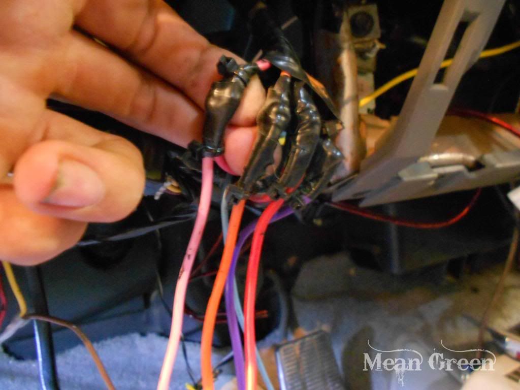 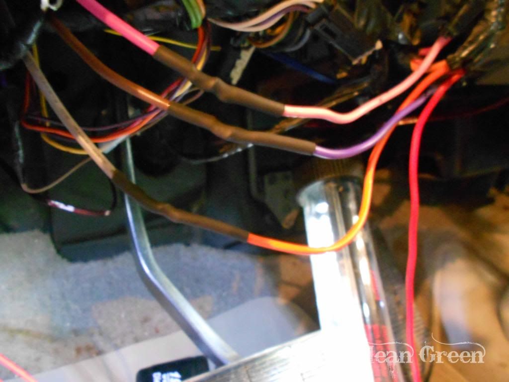 ------------------------------------------------------------------------------------------------ Now you have a few more things to do and you are DONE! You should have 3 things left to do now, install the antenna for the unit, install the hood pin switch, install the valet/program switch, and the status LED. First I'll go over on how to install the antenna. You are going to want to mount the antenna itself in the middle of the windshield on top above the rear view mirror, your going to want to be at least 1" away from the windshield frame. Alright first your going to want to pull off the driver side A-Pillar cover. This cover is held on by metal clips, it is a PAIN to remove. BE CAREFULL so you do not brake any of the fragile clip mounting points. Basically you pull straight away from the pillar to remove them, just take your time and be careful. After you have the pillar out of the way, I'd recommend to mount the antenna. The antennas generally mount to the windshield by using a piece of double sided tape. Razor blade the windshield and clean thoroughly in the location your mounting the antenna for good adhesion. Mount the antenna, and proceed to the following step. Route the wire(s) from the antenna straight to the edge of the headliner. It is best to start on the far drivers side edge of the headliner, and work your hand above the headliner releasing the Velcro that holds the front edge up, to gain access to tuck the wires under the headliner. After the headliner is released, work your way accross tucking the wire(s) from the center till you get to the A-Pillar. Then run the wire(s) for the antenna down the driver side a Pillar. I recommended fastening the wire(s) to the A-Pillar itself so that they don't get accidentally pinched. Small strips of duct tape will suffice. Then drop the wire(s) down through the dash and connect to your remote start unit. Then re-install the A-Pillar cover and you are done with this step! Picture of Antenna Mounted: 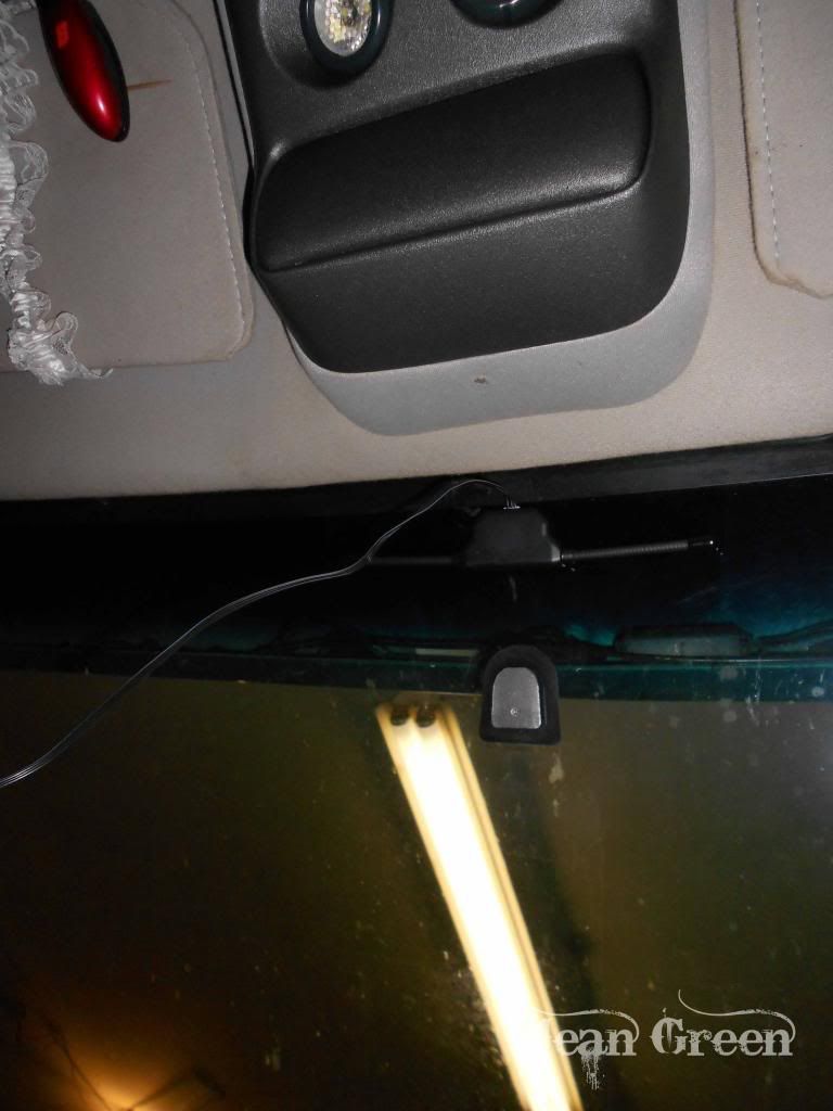 Picture of wire routing down A-Pillar (Note that the other wires in this picture are for the temperature and compass rear view mirror, and 2 are for visor/cab lights): 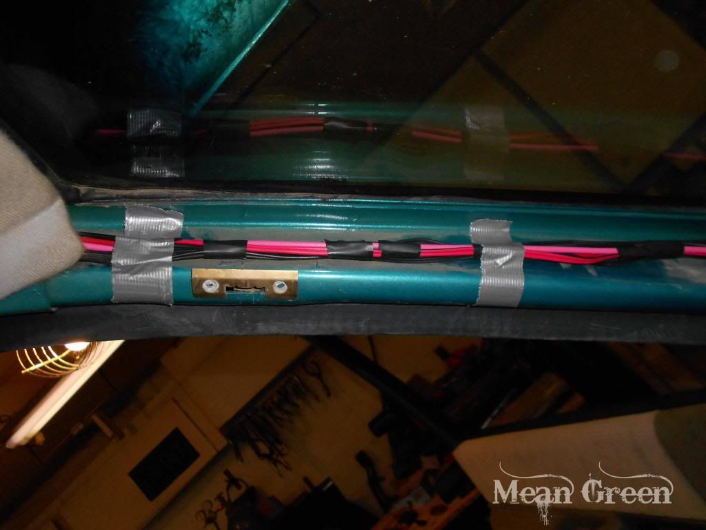 Mirror re-installed and wires ran for antenna: 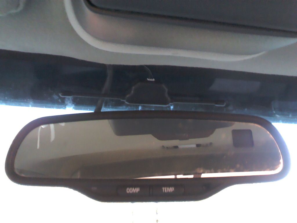 ----------------------------------------------------------------------------------- Now it's time to hook up your Valet Switch and Status LED. I personally used the valet switch one time to program the unit, and then zip tied it under the dash. As it is not something your likely to use all the time, and will save you a hole drilled in your dash! I opted to mount the status LED in one of the knock out plates below the HVAC Controls. This is also a good theft deterrent, so you want it in plain sight if possible. --------------------------------------------------------------------------------- Last step of the install!! You still need to mount your hood pin switch. You have quite a few options on where to mount this. I personally choose to mount it on the the core support. I bent up a bracket out of metal strapping, to allow the switch to fully be depressed when the hood is shut. After you mount this, connect it to the wire that you ran through the firewall for the hood pin switch earlier. The hood pin switch is at 0V GROUND when the hood is OPEN. This will automatically turn off/disable your remote start unit if the hood is opened. Bracket: 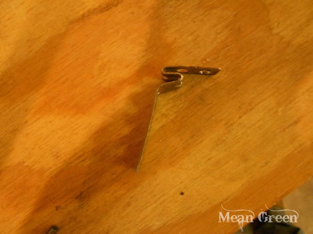 Switch mounted on rear edge of core support:  ---------------------------------------------------------------------------------- And now you have successfully installed your remote start unit!! Re-install your dash panels and make sure that NO wires get pinched or stretched in the process. It is a good idea to test the unit and program it (Tach Learn etc) before putting everything back together also. You will likely have to program the unit now, such as your Tach learn and feature programming. So please consult the remote start's owner manual for programing instructions. Again, I cant stress how important good connections are and that they are well insulated! Now enjoy getting into a cool truck in the summer, and a warm truck in the winter! I hope this article will help people who are interested in installing a remote start unit! They are very nice to have, especially in the winter months if you live in a cold climate like myself and are also very nice for getting your truck cool in the summer months! If you have any questions, just post in this thread and we'll do our best to help answer any questions you may have!! Thanks for taking the time to read this, and hope this can help you! -Baron with VH Coachworks |
|
|

|
 |
| Bookmarks |
| Tags |
| electrical, interior, relays, remote start, wiring |
|
|