
|
Register or Log In To remove these advertisements. |
|
|
|
|||||||
 |
|
|
Thread Tools | Display Modes |
|
|
 04-24-2015, 11:21 PM
|
#1 |
|
Senior Member
 Join Date: Jul 2009
Location: Athens, AL
Posts: 499
|
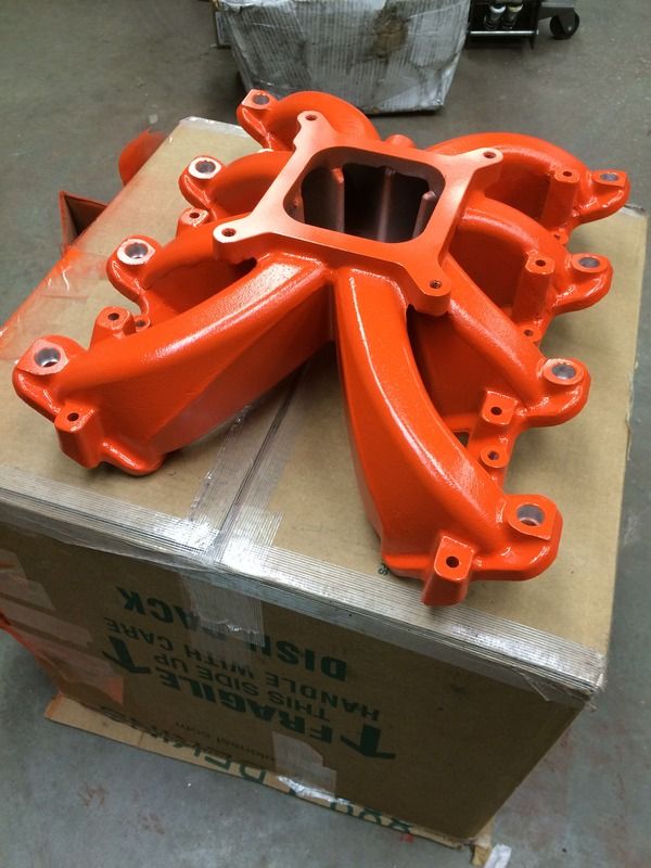
Intake: Part II
Back to the intake. I couldn't stand the aluminum intake. So, I filed off the Holley logo and painted it orange:
 The Holley fuel rails come with two sets of brackets; tall for LS1 and short for LS3 style. The truck injectors are in between those sizes. So I had to cut down the LS1 brackets. In the next photo, LS3 on the left, LS1 on the right and the cut down "truck" size in the middle: 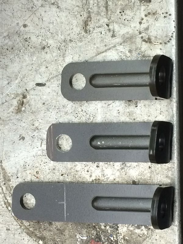 Here's the fuel rail mounted to the intake. Note that the injector wiring is different from left to right. I was trying to determine which way looked better: 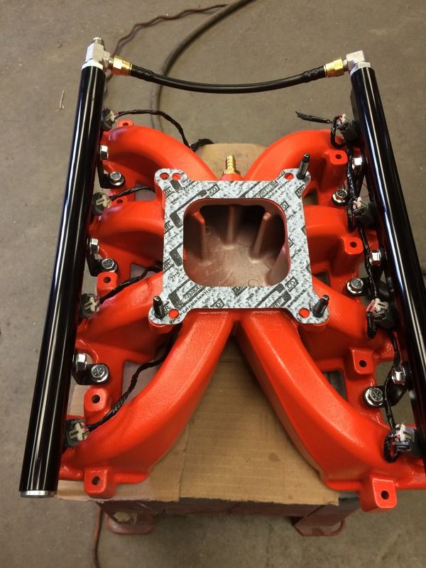 Back to the TB. First, the Holley intake only has a single vacuum port (3/8 NPT). I needed to hook up my PCV system and brake booster, so I didn't really have a place to mount the MAP sensor. In the picture below, the red line represents the square bore of the intake and the black oddly shaped area represents a "relieved" area on the backside of the TB. So, I drilled a 1/8 hole where they intersected and then drilled/chamferred a hole in the TB to accept the MAP. 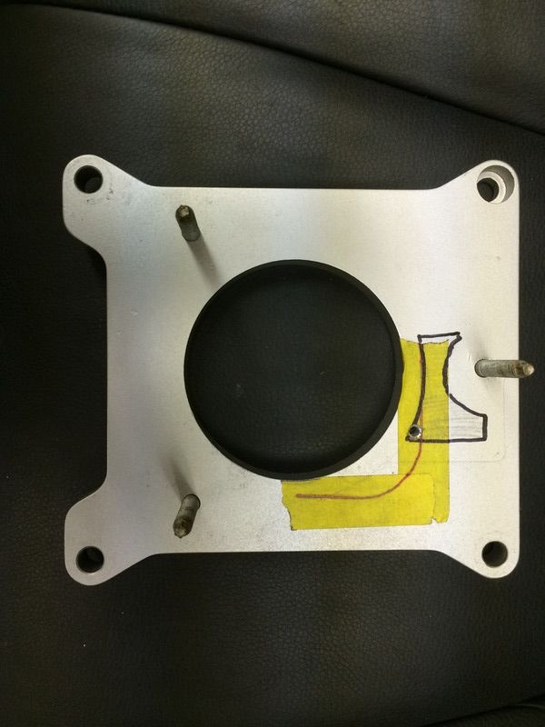 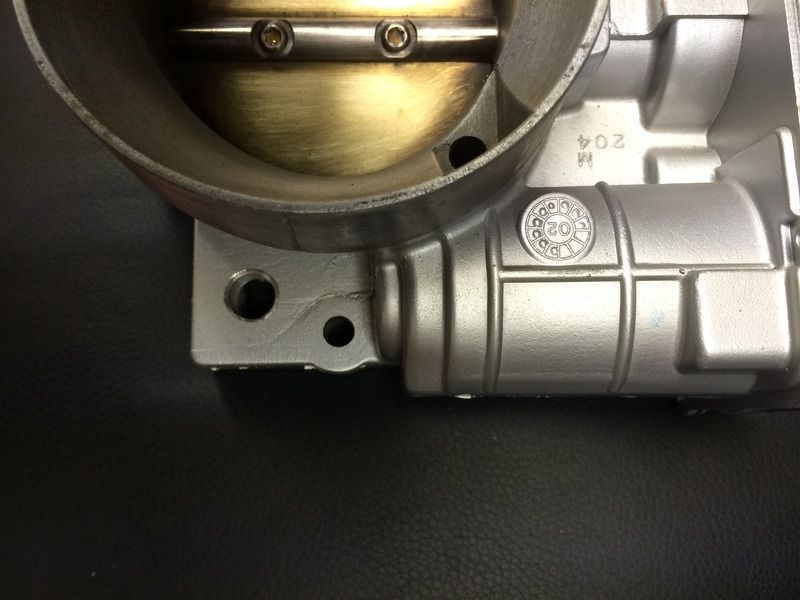 I don't have a pic, but a simple "Z" bracket held in place by the upper TB mounting bolt secures the MAP and keeps if from falling out of the TB. Here's a pic of the air cleaner mounting ring on the TB. I found out really quickly that, being a cast part, the TB has draft (i.e. it tapers smaller toward the top) and it isn't round. So, it took a significant amount of time to hand fit the ring to the top of the throttle body and get a tight interference fit. I literally used machinist's die and emery cloth to get it just right. 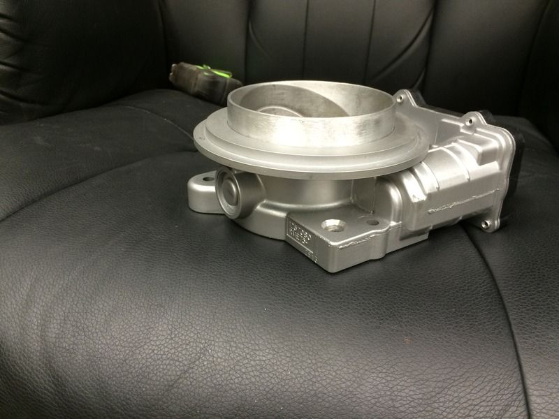 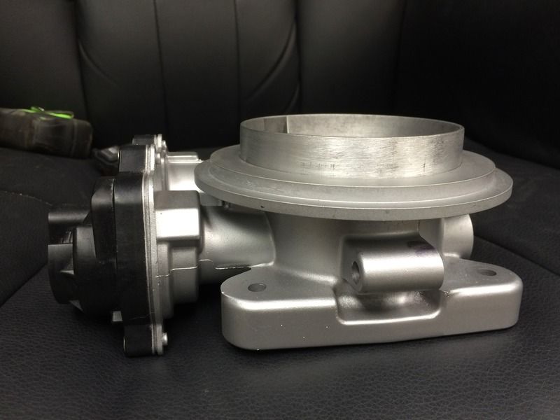 Here's what it looked like on top of the engine. Note that it doesn't have the rail brackets (or even all of the injectors) in this pic, but it gives the idea what it looks like. 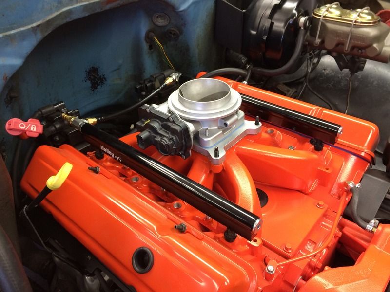
|

|

|
|
04-24-2015, 11:33 PM
|
#2 |
|
Senior Member
Join Date: Jul 2009
Location: Athens, AL
Posts: 499
|
More TB/Intake
I initially planned on running speed density. However, my tuner assured me that on this particular setup, he could give me a better tune using the MAF and told me to couple it directly to the TB (inside the air cleaner). I'll go ahead and say that he was right because I've logged over 200 miles in the last week and it's running perfectly.
Anyway, here's the MAF with a silicone coupler holding it directly to the MAF: 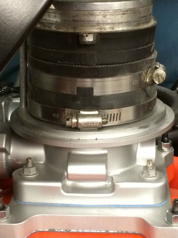 Here it is with the breather base in place (note the offset rod for attaching the breather lid and the MAF wiring coming through the air cleaner base): 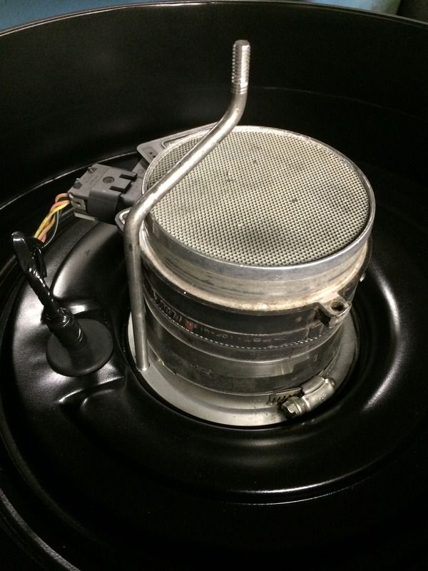 I also had to tap the TB above the blade for the fresh air side of the PCV system:  Here's a not-so-good picture of the "Z" bracket holding down the MAP sensor in the base of the TB: 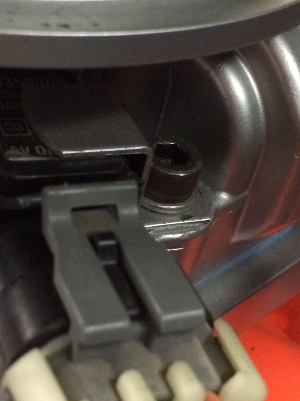 Here's the air filter: 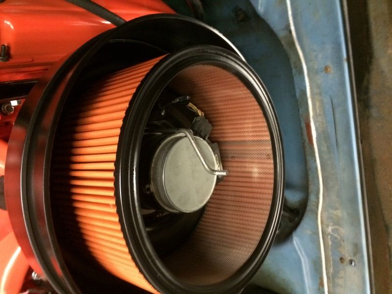
|
|
|
|
|
04-24-2015, 11:47 PM
|
#3 |
|
Senior Member
Join Date: Jul 2009
Location: Athens, AL
Posts: 499
|
Wiring
I don't have a lot of photos of the wiring, but it isn't all that different from any other project. With relocated coils, TB, etc, it made the most sense to just split the harness into circuits.
I started by removing the PCM connectors and labeling all the wires. 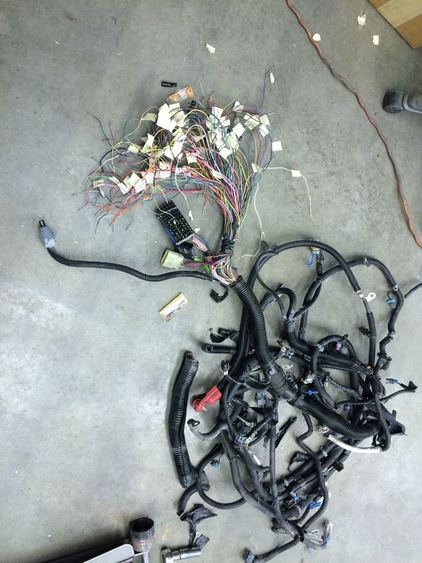 I removed all the tape and loom and split the harness into individual circuits: 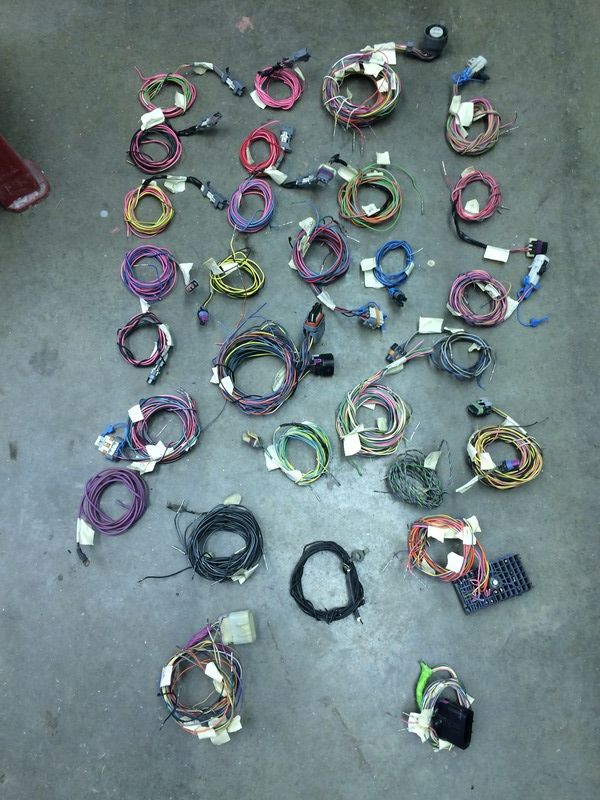 Then I started putting everything back together. The wires that are furthest away are the temp sensor and alternator plugs. The point where everything splits off like spider legs is on top of the bellhousing. 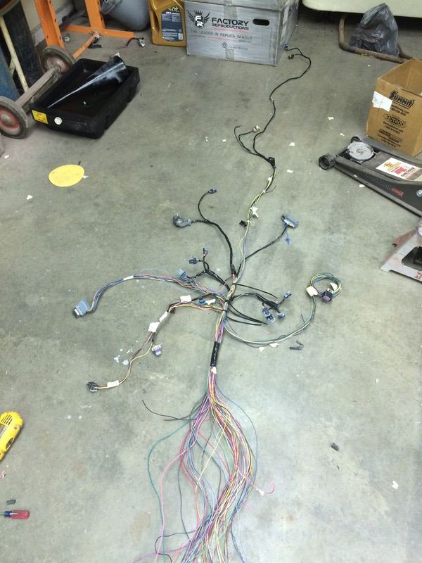 With the coils in back of the engine and the TB on top, most of the wires are hidden without even attempting to hide anything. The harness goes through the firewall in the two factory holes where the oil pressure line and the wiper vacuum lines used to pass trough. I put my PCM under the glovebox and my TAC on the pedal brace under the steering column. |
|
|
|
|
04-24-2015, 11:57 PM
|
#4 |
|
Senior Member
Join Date: Jul 2009
Location: Athens, AL
Posts: 499
|
Gauges
My gauges look stock, but I converted the speedometer to an S10 electric speedo similar to the way ls1nova does it and I used a volt and oil pressure gauge out of a square body ('86) cluster with the '72 faces on them.
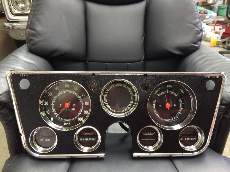  I also modded the fuel gauge to change the "BRAKE" warning light to a little something special for my Check Engine light: 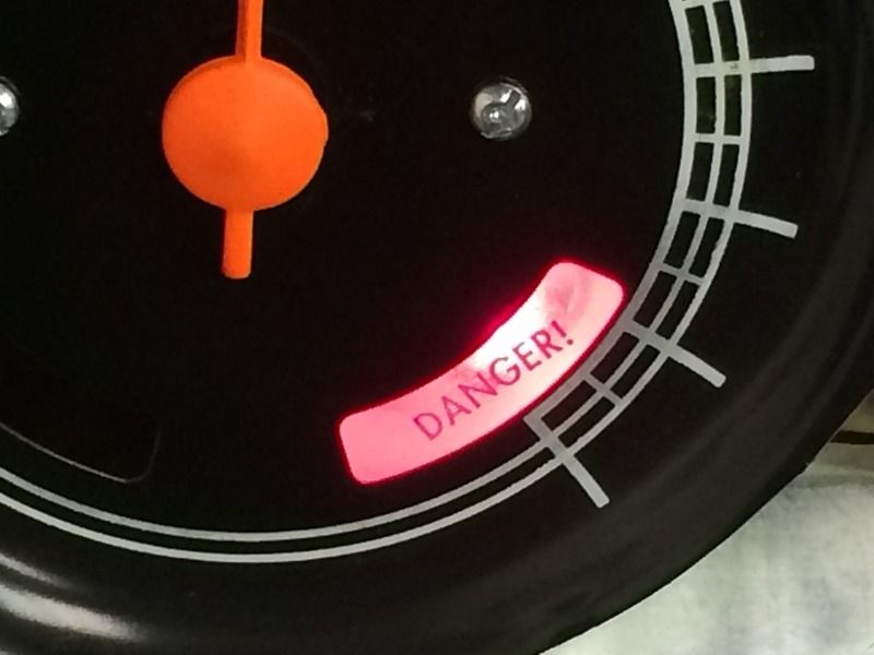
|
|
|
|
|
04-25-2015, 12:09 AM
|
#5 |
|
Senior Member
Join Date: Jul 2009
Location: Athens, AL
Posts: 499
|
Air Cleaner
My air cleaner is made from two breathers from some '90s model TBI trucks.
I started by cutting off the snout and the bottom out of one air cleaner to get just the "ring": 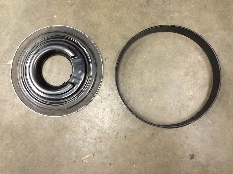 I then removed the snout from the other air cleaner and filled the snout holes: 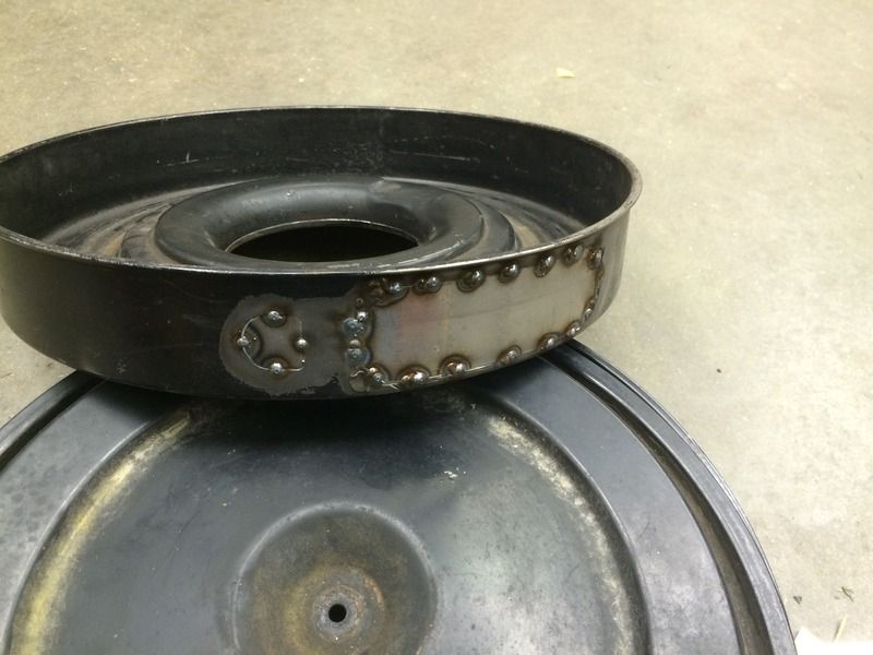 I stacked the ring from the first photo above into the base from the second photo and plug welded them together. After lots of weld smoothing and some paint, I ended up with something that looks like an old oil bath air cleaner. It pulls air in through the 1/4" gap between the lid and base: 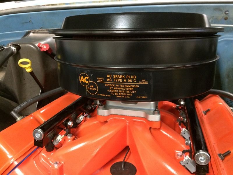
|
|
|
|
|
04-25-2015, 12:14 AM
|
#6 |
|
Senior Member
Join Date: Jul 2009
Location: Athens, AL
Posts: 499
|
Finished Product
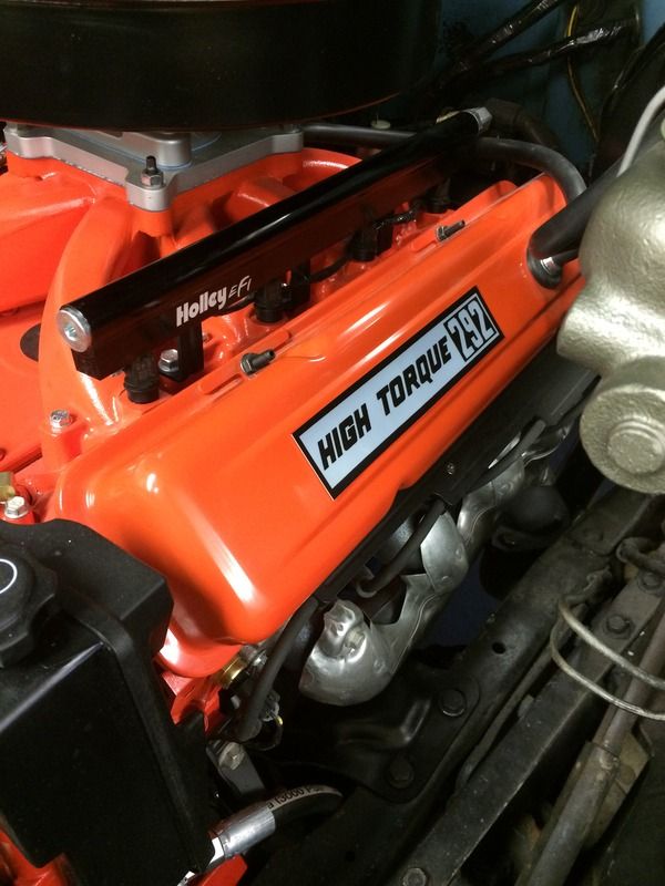
I added some vintage 292 decals to the valve covers:
 And here is is with everything in place (including the wiring) and I've put about 200 miles on it this week. It's running great. 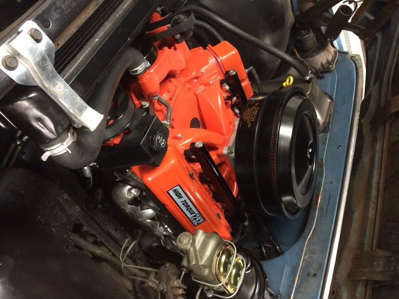
|
|
|
|
|
04-25-2015, 12:59 AM
|
#7 | |
|
Registered User
Join Date: May 2009
Location: Fayetteville, NC
Posts: 725
|
Re: Finished Product
Quote:
 One more question. What radiator did you use? I seen you covered it when you talked about the fans but I was wondering what you did about the steam port. I am researching LS swaps and I keep seeing "steam port" come up. Dunno what it is but seems you gotta have it.
__________________
Jason TEAM C10 HOT ROD POWER TOUR
689 Short Step 68 Step Trucks Sold: 70 GMC, 72 K5 Members met: Andy4639 GCncsuHD CSGAS zicc1835 hotrod farm truck Mingrao Bhelton brenthiggins |
|
|
|
|
|
04-27-2015, 06:18 PM
|
#8 |
|
Registered User
Join Date: Oct 2012
Location: Miami, Florida
Posts: 915
|
Re: Finished Product
And here is is with everything in place (including the wiring) and I've put about 200 miles on it this week. It's running great.
I read the information on the single pane intake, from Holley's website. Holley claims that the operating rpm range the Holley 300-137 is from 2500-7000. the dual plane intake rpm range is 1500-6500. How does this affect drivability? since my current setup is LQ4, FI, what is your opinion? |
|
|
|
|
09-13-2016, 04:05 PM
|
#9 | |
|
Registered User
Join Date: Oct 2012
Location: Dunwoody GA
Posts: 34
|
Re: Gauges
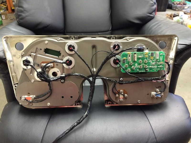
I just stumbled across this build! Awesome build! I have a 69 Stepside Im trying to fix up when I have free time.
I was wondering how you did the lights on your gauges ? Looks like washer and some light socket .. Could you explain a little more on what you are doing ? Thanks!! Allen Quote:
|
|
|
|
|
|
09-13-2016, 11:29 PM
|
#10 | |
|
Senior Member
Join Date: Jul 2009
Location: Athens, AL
Posts: 499
|
Re: Gauges
Quote:
You pretty much nailed what I did. The existing holes in the housing are made for the twist in sockets. You can get pigtails that fit, but they're about $3 each. Sockets like I used are $7 for 10 but they're just a bit to small to fit in the holes. So I used small machine screws to hold down some washers over the existing holes. |
|
|
|
|
|
09-14-2016, 07:27 AM
|
#11 | |
|
Registered User
Join Date: Oct 2012
Location: Dunwoody GA
Posts: 34
|
Re: Gauges
Quote:
Thanks for the quick response and info. |
|
|
|
|
|
| Bookmarks |
|
|


 Hybrid Mode
