
|
 03-25-2013, 10:12 PM
|
#951 | |
|
Registered User
Join Date: Feb 2013
Location: Mandan
Posts: 80
|
Re: Tbi swap build thread
Quote:
|
|

|

|
|
03-25-2013, 10:32 PM
|
#952 | |
|
Registered User
Join Date: Feb 2013
Location: Mandan
Posts: 80
|
Re: Tbi swap build thread
Quote:
|
|
|
|
|
|
03-26-2013, 02:30 AM
|
#953 |
|
Registered User
Join Date: Oct 2003
Location: OC CA
Posts: 1,374
|
Re: Tbi swap build thread
@BigrobDog
OK - thanks for posting photographs - these help quiet a bit. In Photo # 1 Your 1990 burban donor came equipped with CS-130 Alternator. This alternator has internal regulator. OE external '72 regulator that you have in Photo #2 will not be used. To adapt CS 130 to the '72 wiring is actually straight forward, but it will require a bit of DIY soldering. Are you up for it???? CS130 alternator is rated for 105AMPS maximum output and will deliver around 30 to 35Amps at idle. Which is plenty. Look at the back of alternator. There, you should see BAT terminal and big fat red wire should be running between alternator BAT terminal and terminal block that is part of EFI harness - mounted on the passenger side firewall. I thinks there is one, but it is taped-up and not clearly visible. That wire should have been a part of '90 burban harness. From the firewall mounted terminal block there also should be a big red wire running to starter main terminal - its also should be a very thick red wire - 8AWG. Please take a close look and capture a photo of it in case if it is not connected. A fuel pump relay should be in close proximity to that firewall mounted terminal block. Back to CS-130 alternator. There is a multi pin plug with several wires protruding from it.. Most often it is just a brown 16 AWG wire tied to 'L' terminal. This is a alternator light bulb wire. You can NOT connect this wire directly to the instrument alternator light. This connection can only be made if there is a series 150 to 300 OHM 1Watt resistor ( between alternator plug and instrument cluster alternator light). This is done by disconnecting external regulator plug from OE external regulator module and connecting brown wire from CS-130 'L' circuit with a series resistor to terminal 4 of the OE regulator plug - also brown wire. At least GM was consistent with their wire color schemes over decades! . Schematic below does not show this resistor, but it must be there.  Sometime, there is a larger gauge red wire tied to S terminal - this is a voltage sense line. This wire should be tied to a BAT terminal block on the firewall. Photo #3 This is a tough one - this portion of the harness was connected to 90 burban main feed through block. The wires protruding maybe useless - anti lock computer, windshield wiper motor, temperature sensor, etc. It is best to remove split loom and peel off electrical tape and determine where these wires went. VSS - this is a long discussion in itself. Do you have 700R4 from donor or you still have THM-350/400??? P/N switch - some DIY is involved but can be easily implemented. Search this thread for schematic. //RF
__________________
"The Beast" 1975 Chevrolet C20 longbed 350/700R4! with 3inch body lift Dual Flowmasters Super 40's! TBI retrofit completed (2007-07-29)  New 383CID (+030) 08-304-8 9.5:1CR x36,005 (2012-12-17) |
|
|
|
|
03-26-2013, 06:50 AM
|
#954 |
|
Registered User
Join Date: Feb 2013
Location: Mandan
Posts: 80
|
Re: Tbi swap build thread
no i have the 700r4 . its all suburban put 72 over the top
|
|
|
|
|
03-26-2013, 10:58 AM
|
#955 | |
|
not enough hours in the day
Join Date: Jan 2009
Location: Axtell, NE
Posts: 550
|
Re: Tbi swap build thread
Quote:
__________________
65 K-10 Short Step 68 C-50 70 K-5 85 K-10 & piles of spare parts |
|
|
|
|
|
03-26-2013, 11:08 AM
|
#956 |
|
Registered User
Join Date: Oct 2003
Location: OC CA
Posts: 1,374
|
Re: Tbi swap build thread
Oh wow - it is nice to have a power lift -> CAT!
With VSS you have a small problem. The 90 burban uses electronic speedometer, while '72 truck is a classic mechanical unit. 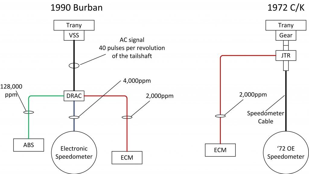 To solve this you'll need to find a mechanical speedometer gear cable unit from an earlier 700R4 and add an inline 2000 ppm VSS unit from JTR.com. For example AC-Delco 25512339. But first you need to figure out which speedometer gears to use before ordering. 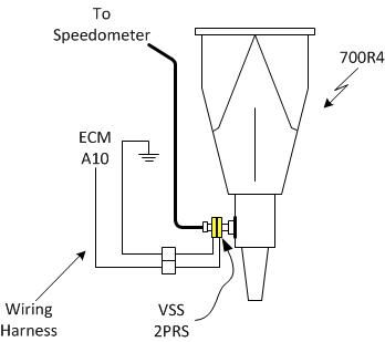 Also complicating conversion is that you have a 4x4 burban and VSS may have been installed in a transfer case (I simply do not know). //RF
__________________
"The Beast" 1975 Chevrolet C20 longbed 350/700R4! with 3inch body lift Dual Flowmasters Super 40's! TBI retrofit completed (2007-07-29) New 383CID (+030) 08-304-8 9.5:1CR x36,005 (2012-12-17) |
|
|
|
|
03-26-2013, 11:17 AM
|
#957 | |
|
Registered User
Join Date: Oct 2003
Location: OC CA
Posts: 1,374
|
Re: Tbi swap build thread
Quote:
http://67-72chevytrucks.com/vboard/s...d.php?t=436742
__________________
"The Beast" 1975 Chevrolet C20 longbed 350/700R4! with 3inch body lift Dual Flowmasters Super 40's! TBI retrofit completed (2007-07-29) New 383CID (+030) 08-304-8 9.5:1CR x36,005 (2012-12-17) |
|
|
|
|
|
03-26-2013, 11:40 AM
|
#958 |
|
not enough hours in the day
Join Date: Jan 2009
Location: Axtell, NE
Posts: 550
|
Re: Tbi swap build thread
Thanks again RF. I hadn't seen that thread. Glad to know this before firing it up and wondering why it didn't charge properly.
__________________
65 K-10 Short Step 68 C-50 70 K-5 85 K-10 & piles of spare parts |
|
|
|
|
03-26-2013, 09:21 PM
|
#959 | |
|
Registered User
Join Date: Feb 2013
Location: Mandan
Posts: 80
|
Re: Tbi swap build thread
Quote:
|
|
|
|
|
|
03-26-2013, 09:53 PM
|
#960 | |
|
Registered User
Join Date: Feb 2013
Location: Mandan
Posts: 80
|
Re: Tbi swap build thread
Quote:
|
|
|
|
|
|
03-26-2013, 09:54 PM
|
#961 | |
|
Registered User
Join Date: Feb 2013
Location: Mandan
Posts: 80
|
Re: Tbi swap build thread
Quote:
|
|
|
|
|
|
03-26-2013, 11:12 PM
|
#962 | |
|
Registered User
Join Date: Oct 2003
Location: OC CA
Posts: 1,374
|
Re: Tbi swap build thread
Quote:
Take a look at your CS-130 plug. 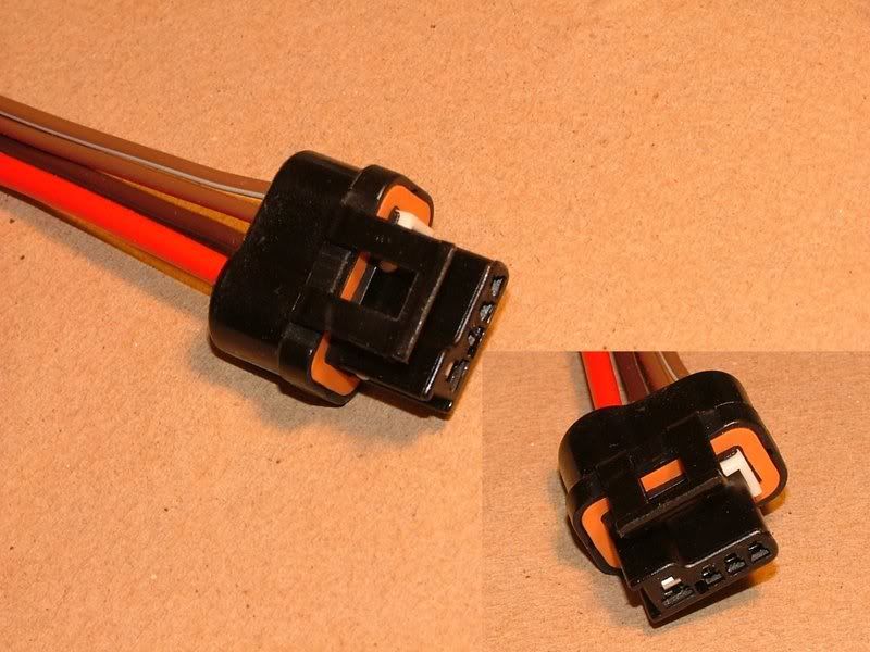 In most case it will have only two wires populated - Large red and smaller gauge brown. The red goes to terminal labeled 'S' and brown goes to 'L'. Terminal letters are hard to see but they are part of plug body!!! Disconnect plug from OE '72 external voltage regulator shown in the photo below...  extend wire from CS-130 plug 'L' terminal to reach terminal #4 of the OE '72 external voltage regulator. //RF
__________________
"The Beast" 1975 Chevrolet C20 longbed 350/700R4! with 3inch body lift Dual Flowmasters Super 40's! TBI retrofit completed (2007-07-29) New 383CID (+030) 08-304-8 9.5:1CR x36,005 (2012-12-17) |
|
|
|
|
|
03-29-2013, 08:21 PM
|
#963 |
|
Registered User
Join Date: Oct 2003
Location: OC CA
Posts: 1,374
|
Re: Tbi swap build thread
__________________
"The Beast" 1975 Chevrolet C20 longbed 350/700R4! with 3inch body lift Dual Flowmasters Super 40's! TBI retrofit completed (2007-07-29) New 383CID (+030) 08-304-8 9.5:1CR x36,005 (2012-12-17) |
|
|
|
|
03-30-2013, 11:12 AM
|
#964 |
|
not enough hours in the day
Join Date: Jan 2009
Location: Axtell, NE
Posts: 550
|
Re: Tbi swap build thread
I wired B8 for the AC signal into the dark green lead to the compressor. Now with the compressor pluged in there is continuity between B8 and B1 which is a 12v battery wire hooked to a junction block and also between B8 and B3 the black/red wire to the distributor plug. Is this normal?
It makes me think the AC would always be engaged. The compressor that is on the engine now is locked up and will be replaced, could this be the cause?
__________________
65 K-10 Short Step 68 C-50 70 K-5 85 K-10 & piles of spare parts |
|
|
|
|
03-30-2013, 03:03 PM
|
#965 | |
|
Registered User
Join Date: Oct 2003
Location: OC CA
Posts: 1,374
|
Re: Tbi swap build thread
Quote:
 It is an input signal to ECM indicating that compressor clutch has been engaged. Move AC control selector and see if this voltage goes away when move AC to heater position (no AC). //RF
__________________
"The Beast" 1975 Chevrolet C20 longbed 350/700R4! with 3inch body lift Dual Flowmasters Super 40's! TBI retrofit completed (2007-07-29) New 383CID (+030) 08-304-8 9.5:1CR x36,005 (2012-12-17) |
|
|
|
|
|
03-31-2013, 10:21 AM
|
#966 | |
|
Registered User
Join Date: Feb 2013
Location: Mandan
Posts: 80
|
Re: Tbi swap build thread
Quote:
|
|
|
|
|
|
03-31-2013, 12:20 PM
|
#967 | |
|
Registered User
Join Date: Feb 2013
Location: Mandan
Posts: 80
|
Re: Tbi swap build thread
Quote:
|
|
|
|
|
|
03-31-2013, 01:31 PM
|
#968 | |
|
Registered User
Join Date: Feb 2013
Location: Mandan
Posts: 80
|
Re: Tbi swap build thread
Quote:
|
|
|
|
|
|
03-31-2013, 04:03 PM
|
#969 | |
|
Registered User
Join Date: Oct 2003
Location: OC CA
Posts: 1,374
|
Re: Tbi swap build thread
Quote:
The TCC wiring diagram will depend on internal harness installed inside 700R4. Depending on application GM had different transmission case harness. And this is why I am not going to even attempt to suggest how to wire up TCC at this time. There is a 'cat' in transmission forum clinebarger - he knows more about 700R4 than GM! Ask him a question about TCC converter harness inside your trany. You'll have to post transmission ID (aka build configuration) stamped on the oil pan flange, back passenger side.  //RF
__________________
"The Beast" 1975 Chevrolet C20 longbed 350/700R4! with 3inch body lift Dual Flowmasters Super 40's! TBI retrofit completed (2007-07-29) New 383CID (+030) 08-304-8 9.5:1CR x36,005 (2012-12-17) |
|
|
|
|
|
04-01-2013, 09:49 PM
|
#970 |
|
Registered User
Join Date: Feb 2013
Location: Mandan
Posts: 80
|
Re: Tbi swap build thread
Rf or cj I got a question , need some help here 72 chevy truck on 1990 suburban fram with tbi .
Q1, fuse next to fuel pump relay, gray wire in and gray wire out fuse in the middle. ok one side is hot other side is ground while truck is off, is this because of the computer . are do u know why this is. Q2, gray box , just up from the computer,3'' long 1 1/2 wide with purple wires going in to it. it opens on one end ,I opened it and it was a small circuit board. Q3, I have my old seedometer and on the back of it is a circuit board attached to it is this my drac,and if so how do i wire this up. |
|
|
|
|
04-03-2013, 10:42 PM
|
#971 |
|
not enough hours in the day
Join Date: Jan 2009
Location: Axtell, NE
Posts: 550
|
Re: Tbi swap build thread
I just tried it for the first time. It fired right up
, but idles at 1,800 RPM The timing is set at 0* the tan/black wire unplugged, but I was checking this at the fast rpm's. I cleaned up the throttle body and put a rebuild kit in it while averything was apart. Other than not getting something right when putting it together I'm at a loss for what would cause this. Any ideas where to look?
__________________
65 K-10 Short Step 68 C-50 70 K-5 85 K-10 & piles of spare parts |
|
|
|
|
04-04-2013, 12:02 AM
|
#972 | |
|
Registered User
Join Date: Oct 2003
Location: OC CA
Posts: 1,374
|
Re: Tbi swap build thread
Quote:
Setting base timing at 1800 RPM is ok for starters, but it is better to do this while engine is idling around 650 RPM. As always check for gross vacuum leaks around intake - PCV, CCP, brake booster line, etc.
__________________
"The Beast" 1975 Chevrolet C20 longbed 350/700R4! with 3inch body lift Dual Flowmasters Super 40's! TBI retrofit completed (2007-07-29) New 383CID (+030) 08-304-8 9.5:1CR x36,005 (2012-12-17) |
|
|
|
|
|
04-04-2013, 07:20 PM
|
#973 | |
|
not enough hours in the day
Join Date: Jan 2009
Location: Axtell, NE
Posts: 550
|
Re: Tbi swap build thread
Quote:
I went through the steps with the IAC removed from the throttle body just to see what happened. The motor ran, but the plunger did not move. I gave it a push and it went in easily, then pulled and it came completely out. I realize I need to get a new one. I ran the engine with the IAC installed after this both with the plunger extended all the way by the spring and again with the plunger completely removed thinking that one of these would bring the idle down. Neither way changed it. How does the IAC work, I assume it closes to cut off excess air and opens just enough to get the right idle speed. I also checked the throttle blades, they are up against the wall of the throttle body with mabey a very small gap. The idle screw still has the cap over it. I don't detect any vacuum leaks.
__________________
65 K-10 Short Step 68 C-50 70 K-5 85 K-10 & piles of spare parts |
|
|
|
|
|
04-04-2013, 08:05 PM
|
#974 |
|
Registered User
Join Date: Oct 2003
Location: OC CA
Posts: 1,374
|
Re: Tbi swap build thread
OK - yes, you'll need to get IAC replaced.
When you go through the IAC reset the plunger should extend fully and close off air bypass passage. You should hear a clicking noise while ALDL pins A & B are tied together and IAC is plugged into the harness. SES light should be on as well. Your assumption about how IAC operates are correct. Lets address IAC operation first before moving any further. I assume that EGR valve is installed, but vacuum hose is disconnected??? The other items to be aware of - make sure that all harness ground connections are tied to their respective grounds. There are two main ones - in front by the thermostat housing and one in the back of the passenger cylinder head. Loose grounds will drive ECM nuts!!! //RF
__________________
"The Beast" 1975 Chevrolet C20 longbed 350/700R4! with 3inch body lift Dual Flowmasters Super 40's! TBI retrofit completed (2007-07-29) New 383CID (+030) 08-304-8 9.5:1CR x36,005 (2012-12-17) |
|
|
|
|
04-04-2013, 08:23 PM
|
#975 | |
|
not enough hours in the day
Join Date: Jan 2009
Location: Axtell, NE
Posts: 550
|
Re: Tbi swap build thread
Quote:
The EGR valve is installed and the vacuum hose is connected. Should it be disconnected for this? I will double check grounds at the ecm plug.
__________________
65 K-10 Short Step 68 C-50 70 K-5 85 K-10 & piles of spare parts |
|
|
|
|
 |
| Bookmarks |
|
|


 Linear Mode

