
 |
|
|
#101 |
|
Registered User
Join Date: May 2009
Location: Grey County Ontario
Posts: 207
|
Re: Project Fargolet
Thanks guys! I spent a lot of time on this site before starting to work on the Fargolet, just reading other people’s build threads to get ideas about how to do stuff, and it saved me a ton of time and aggravation. Forums like these are the greatest way to swap info and ideas.
Joedoh, those windshields really are a PITA to work on. I lucked out as mine was salvageable and I ended up with less than 200 bucks in it for glass, seal, setting tape and sealant. The alternative was a new one which would be pushing 2 grand by time I got it in my hands here in Canada. And Tempest67, you were right, that stuff around the driveshaft is carbon fiber! Made some more progress in the last couple of weeks. We installed the windshield glass which went quite well. We then got the seal pressed into the groove around the frame (very slow work with a screwdriver to press it into place), and then we mounted it. The seal is new and stiff, and the fact that my shed is kept at 55 degrees doesn’t help soften that rubber. Pet Peeve: There are 6 different ways that the windshield seal can be attached to the frame, 5 of which are wrong. Would it kill the suppliers to include a sketch? Here’s the results:   The doors are on in the above picture, as I did some work on the hinges. A couple of the hinges were badly worn, allowing some sag. I will likely need to do a bearclaw latch install soon, so that sag had to be taken care of first. The worst offender was the driver door bottom hinge, which had worked its way into a nice egg shape:  I have a drawer with assorted sleeves in it (no idea where I got them!), and I was lucky enough to find one that fit like a glove (after a little grinding that is).  Good as new!  And now, fun with gauges! I had been putting off dealing with gauges for a while, and finally decided to get at it. While I have been trying to use everything from the S10 donour, I ran into a snag here. The speedometer looked doable, but the odometer is part of the tach assembly. My dash has one large round hole for a speedo and no spot for a tach (and I don’t particularly want a tach anyhow). I need an odometer though, so I opted to order a new speedo/odometer. After a bunch of research I decided to use a gps style as this bypasses issues with matching electronic signals. The one I ordered also happened to have built in lights for turn signals and high beams, thus saving me from more fabbing. Here it is, along with a filler ring (new speedo is smaller than the old, so a filler was needed). I will use the filler as a spot to mount a few warning lights later on.  To get a good signal, the gps receiver needs to “see” the satellites above, but the Fargo has a vertical windshield and I suspected reception may me spotty at best. I did however have a rather convenient outside location with a wonderful view straight up (my ammo box fuel filler), and the gps cable was long enough to reach.  The other 4 gauges took a little more thinking. In keeping with the theme of the build, I wanted to reuse the S10 gauges as they worked fine and were compatible with all the senders (and of course they were free!). This turned out to be a fiddly job, but interesting and actually fun. Here’s what I did, (and keep in mind that this is a ‘96 donour, so I can’t say if it works for the square bodies or the ‘98 and onwards types). First came the S10 instrument panel disassembly. This is just a matter of removing the torx screws on one side, and then separating the 2 halves of the panel by pushing down on all of the gauge studs bit by bit until the 2 halves come apart:   Removal of the gauges involves 2 steps. First the needle has to be removed. Here is a shot of the needle being pulled off of its mount by a special tool. If anyone wants one of these tools, send $30 and a stamped, self addressed envelope to me and I will provide one. 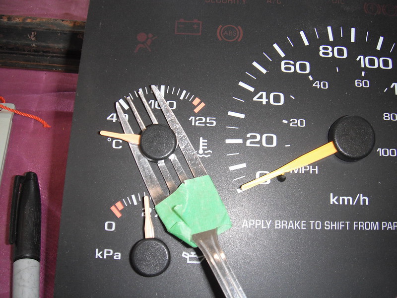 Once the needle is off, the gauge can be unscrewed by a #8 Torx driver (or some really tiny socket). The screws are some kind of self tapping jobs that hold the gauge into the plastic panel, and they are very slim. Here’s an S10 gauge. Its small, and its deeper than the original gauges in the Fargo:  Next I had to figure out how to mount the S10 gauges using the Fargo housings. The old gauge faces were incompatible with the new gauges. The Fargo gauges are mounted upside down (the needles point downwards) and the needles rotate counter clockwise. S10 gauges (and pretty much all others) point up and rotate clockwise. Here is an original gauge panel:  And here is how the original gauges and panels went together:  I got a piece of plastic (no idea if it's plexiglass or lexan) and cut it to fit the shape of the back of the gauge housings. After a ton of very careful measurements I was able to drill out holes for the gauge needle shaft and for the self tapping screws (they need starter holes or you will snap them). The drill bit for the self tapping screws was so small that it would not hold in any chucks I had, so I ended up putting the bit in a dremel with an extra small collar. The gauges could now be affixed to the rear of the housings. Here’s one of them temporarily screwed in place:  For the gauge faces I could have cut up the S10 panel and tried to use those, but I wanted something that looked a little more period-correct. I took a bunch of measurements and then enlisted my wife to help me out with decals. She is a whiz on the computer and after a couple of hours we had our new faces. We printed them out on paper to let me test the fit, and once I was happy with it we reprinted them on clear, self adhesive label sheets (Avery brand). They worked OK, but they don’t print a deep enough black colour. Perhaps I’ll try a different brand in the future.The inside of the housing had to be painted, and the original 6 volt bulb replaced with a 12 volt one: 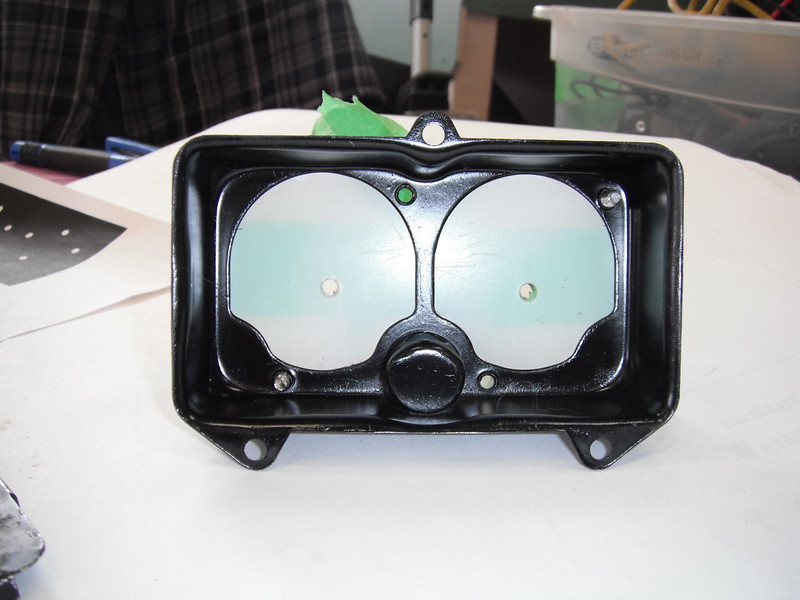 Here is one of the clusters with the lower face sheet in place. The 3 dots align exactly with the S10 gauge high, low and mid points and they sit directly under the needle:  Here is that housing with just the voltmeter installed. To get the needle in the correct spot we grabbed a car battery and tested its voltage, then hooked up the gauge and set the needle to correspond to the reading we got on the battery. Attaching these needles is simply a matter of pressing them onto the shaft (no tools required).  Another decal then gets placed on a thin sheet of plastic that covers the housing, and this sheet labels the gauge. The Fargo housing cover holds this sheet of plastic in place.  When it's all put together it looks like this (only one gauge installed right now as I had not yet gotten to debugging everything).  Next came figuring out how to attach wires to the studs that power the S10 gauges. I was having a tough time finding the special clips that will attach to studs until I posted a query on the 47-59 Board. Another member found them for me (thanks 1project2many !) but they appear either unavailable or out of stock right now and I needed them right away so I had to improvise. I can always switch to the good clips later as I always leave sufficient wire to fix screwups down the line. Here’s what we did for now (my son Brian was providing his engineering expertise and it’s a good thing. He can instantly make out what’s happening in a wiring diagram, and he is crazy good at micro soldering). Brian brought up a bunch of these tiny round connectors (neither of us know what they are called), and it turns out that they fit nice and snug on the S10 gauge posts:   From this point it was just a matter of wiring up the 2 gauge pods containing the oil/temp/volts/fuel gauges, as well as the new speedo and then adding loom. Each gauge pod has its own connector so that removal is easy.  Next came the Prindle (the PRNDL indicator). It's always nice to be able to tell what gear you have selected, so this unit had to come out of the S10 cluster and into the Fargo. The prindle is run by a big circuit board within the S10 instrument panel, and the best option seemed to be taking the entire thing out and mounting it in a flat spot behind the dash. Here’s how we did it. This plug provides the electrical inputs that the pringle needs:  The plug was depinned:  And the plug was attached to quick connects that led to the S10 harness:  The prindle assembly sits in a plastic box that Brian created on a 3D printer. 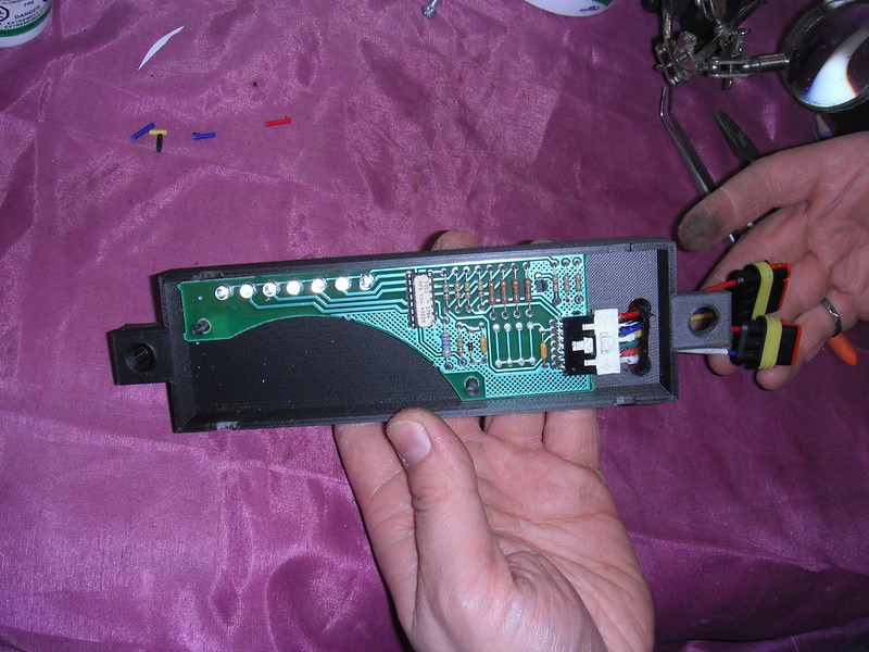 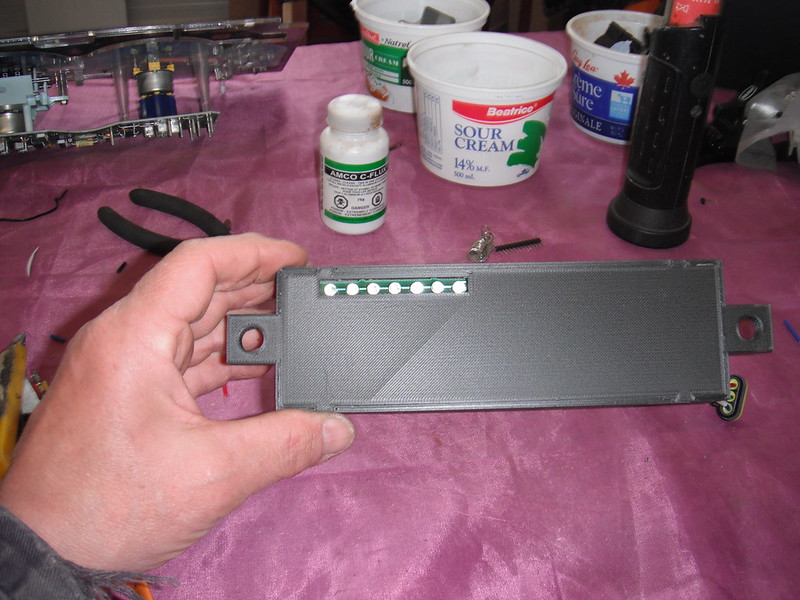 There was a convenient big, empty flat spot on my dash that would easily accommodate the prindle assembly. To mount it I welded 2 studs into the inner face of the dash so that installation or removal just involved loosening 2 nuts and unhooking the quick connector. To be able to see the lighted display I would have to cut a narrow slot into the dash. I was initially reluctant to do this (I hate cutting original antique metal), but then realized how silly this was. Right above the spot where the prindle display slot would sit is a giant hole cut into the dash by some previous owner, and from the quality of the cut I suspect he did his bodywork with a chainsaw. I stopped overthinking things and just got to work cutting the slot into the dash. The hole still needs to be cleaned up, and I have to create some sort of cover that labels the leds that indicate the gear it’s in.  Here’s where it all sits now:  The ring around the speedo has 3 holes for small LED warning bulbs. I had picked up some bulbs but after setting them in place and seeing how they looked I ripped them out (they looked like they belonged in a Honda Civic with a whale tail spoiler and a 4 inch exhaust pipe!). I will find something a little more subtle. After looking at my work, I got to thinking about Gauges model 2.0. I think I will play around with a different design that mounts the gauges deeper into the housings. It will be a little trickier as this obscures the internal light somewhat, but I think I will get a better look that way. I also have to find transparent sheets that can accept black ink better when I print them. For now though I know that I can reuse the S10 gauges, and pulling these out to make them better will be a fun winter project next year. For now I really just wanna go drive this thing. More to follow! |
|
|

|
|
|
#102 |
|
Registered User
Join Date: Sep 2019
Location: Maynooth, Ontario, Canada
Posts: 174
|
Re: Project Fargolet
Good work, always tricky reworking old gauges.
__________________
http://67-72chevytrucks.com/vboard/s...82#post8619382 |
|
|

|
|
|
#103 |
|
Registered User
Join Date: Nov 2014
Location: somewhere, PA
Posts: 1,088
|
Re: Project Fargolet
very nice work on the gauge rebuild, that's proper hot rodding there
|
|
|

|
|
|
#104 |
|
Registered User
Join Date: Sep 2018
Location: Ontario
Posts: 833
|
Re: Project Fargolet
Great workmanship on the gauges. I hope they work for you.
Keep it going, looking good
__________________
https://67-72chevytrucks.com/vboard/...=797726&page=3http://https://67-72chevytrucks.com/...=797726&page=3 51 Chev 5 window on S10 with SBC 1958 Pontiac Wagon build https://67-72chevytrucks.com/vboard/...d.php?t=849781 |
|
|

|
|
|
#105 |
|
Senior Member
  Join Date: Oct 2014
Location: Eagle, ID
Posts: 3,017
|
Re: Project Fargolet
Nicely done.
|
|
|

|
|
|
#106 |
|
Senior Member
 Join Date: May 2007
Location: Doodah Kansas
Posts: 7,774
|
Re: Project Fargolet
beautiful work! great problem solving again!
__________________
the mass of men live lives of quiet desperation if there is a problem, I can have it. new project WAYNE http://67-72chevytrucks.com/vboard/s...d.php?t=844393 |
|
|

|
|
|
#107 |
|
Registered User
Join Date: May 2009
Location: Grey County Ontario
Posts: 207
|
Re: Project Fargolet
With the gauges sorta done (I believe I will do a nicer version in the future), it was time to finally wrap up the rest of the wiring. One area that I knew was going to be bad was the cowl lights. This was the only part of the entire truck that had any serious rust. The light housings themselves were OK, but the inner reflectors (that the bulb sockets snap into) were completely shot:
 I was going to try to make my own, but then I discussed it with my son Brian and he told me to give him one of the rusty old reflectors and leave it with him. Not long afterwards, he surprised me with these:  He used the 3D printer to whip up a set of new reflectors. For a shiny backdrop to reflect light I simply used shiny silver spray paint. The original cowl lamps were just parking lights with a single contact bulb. The squeeze style of socket for the bulb is still available (Dorman model 85804, a whopping $1.81 at Rockauto!), however a dual contact plug is also available (Dorman model 85802). By switching to the dual contact plug, and using miniature bulbs (Wagner B1007) that fit inside the very limited space, I was able to convert the cowl lamps to be both parking and signal lights. It was actually quite easy, as the S10 harness obviously had provisions for both, so it was simply a matter of routing the existing wires to the cowl lamps and adding a 3rd wire to each socket in order to provide a proper ground. This was necessary as the new reflectors are ABS and won’t allow the cowl lights to body ground as they were originally designed to do. Here’s the old vs the new:  The headlight pods were in good shape, so all I did was clean them up, retap all the holes and put in new 12 volt sealed beams and new sockets. I’m adding weatherproof quick connectors as well for a very good reason. The engine in this thing is fairly buried, and even simple jobs like changing spark plugs would involve some fairly miserable leaning over and trying to access things. With the front fenders off, access is fantastic and comfortable (I can actually pull up a chair and sit and work on the engine). Removing the front fenders on this thing is painfully easy (it’s just a few bolts), so adding a way to unhook the headlights (which are mounted on the fenders) makes it ever so easy to pop off a fender in a minute or two. At the tail end I did the same thing so that I can remove fenders and bedsides easily. I also wired in weatherproof connectors for reverse lights. At night it’s pitch black here (I need a flashlight to go from my shed to my house), so decent reverse lights are a must. At this point I had working exterior lights, and now it was time to instal a single old-style headlight switch to replace the S10 switches. The S10 has a big, ugly, plastic toggle and dial combo switch, Ugh!!!!:  I dreaded this wiring task, but as usual my imagination made it out to be far more difficult than it actually was. I’ll detail what I did here, along with an explanation in case anyone else doing an S10 swap could use a short guide. Remember that this is a 1996 S10 so other years may differ. As well, a wiring diagram is an absolute must for this kinda fooling around! The S10 switch is actually 2 switches-one for lights and one to dim the instrument panel. Here is the headlight switch, with brown, red, yellow and 2 orange wires (the 2 orange wires actually share the same connector pin):  The replacement headlight switch I chose is for a 1970 C10 but the same (or pretty much the same) switches were used over a huge time frame by GM. The spade connectors are numbered on the switch. Here’s what I did: The big red wire in the S10 switch gets power from a fusible link. I removed this from the S10 switch and installed it in location #1 on the new switch. The brown wire in the S10 switch feeds everything but the headlights. I removed the brown wire from the S10 switch and attached it to position #4 on the new switch. The S10 switch has a double orange wire (2 orange wires enter together at the same pin). I removed these from the S10 switch and attached them in location #5 on the new switch. The yellow wire in the S10 switch powers just the headlights. I removed this and attached it to location #6 in the new switch. For the cowl lamps (which are now dual filament bulbs to provide parking and signal lights) it got a little more interesting. My cowl lights are white, so they are not allowed to be on while the vehicle is in motion (only a problem at night when the headlights are on). To power the parking lamp filaments of the cowl bulbs, I cut the brown S10 wire that feeds them at the main firewall pass-thru, and ran a fresh brown wire to them from location #7 on the new switch (this position only has power when the knob is pulled out to the first detent). The S10 instrument panel dimmer dial switch has 4 wires, and it controls both the on/off of the dome light and the dimming of the instrument cluster lights:  By removing the white wire from the S10 instrument panel dimmer switch, and connecting it to position #0 on the new headlight switch, the dome light works. The black wire on the S10 dimmer switch is just a ground that isn’t needed. I am keeping the entire S10 dome light assembly as the Fargo one was trashed. The other 2 wires from the S10 instrument panel dimmer switch (brown and dark green) control the dimming of the instrument cluster lights. I only have 3 small bulbs in my gauges, so after cutting out the S10 instrument panel dimmer switch I simply connected the brown to the dark green wires, thus giving me a full 12 volts to those lights. If I had wanted the dimming feature, it would just be a matter of attaching the dark green wire from the S10 dimmer switch to location #2 on the new headlight switch. Here’s a shot of the process as I was figuring things out:  I did it one wire at a time, and I confess that I flinched every time I reconnected the battery (I fully expected to blow some fuses as electrical stuff is not my strong suit). After each wire was installed and the battery reconnected I switched stuff on and off and made sure that everything was still OK. 6 wires later I was all done and everything worked. More to follow! |
|
|

|
|
|
#108 |
|
Registered User
Join Date: Sep 2019
Location: Maynooth, Ontario, Canada
Posts: 174
|
Re: Project Fargolet
You are doing a mighty fine job. Like to see it up close when your all done.
 : :
__________________
http://67-72chevytrucks.com/vboard/s...82#post8619382 |
|
|

|
|
|
#109 |
|
Senior Member
 Join Date: May 2007
Location: Doodah Kansas
Posts: 7,774
|
Re: Project Fargolet
thanks for the tutorial, I usually just screw the og s10 switch under the dash haha
__________________
the mass of men live lives of quiet desperation if there is a problem, I can have it. new project WAYNE http://67-72chevytrucks.com/vboard/s...d.php?t=844393 |
|
|

|
|
|
#110 |
|
Registered User
Join Date: May 2009
Location: Grey County Ontario
Posts: 207
|
Re: Project Fargolet
Thanks olecarguy! When I get this thing on the road, and they finally reopen car shows and cruise nights it will be a blast to see each others trucks. There’s a bunch of Southern Ontario builds on this board I’m dying to see. OK, Maynooth ain’t exactly Southern Ontario, but it's still doable!
|
|
|

|
|
|
#111 | |
|
Registered User
Join Date: May 2009
Location: Grey County Ontario
Posts: 207
|
Re: Project Fargolet
Quote:
If I’d only thought of doing that, I could have easily built a small bracket for the bottom of the dash and placed the S10 switch there, within easy reach yet hidden. Then I could have just stuck the old, non functioning Fargo headlight switch back in its original spot and it would have looked bone stock. Would have saved me a lot of time, and a bit of money. Nuts……... |
|
|
|

|
|
|
#112 |
|
Registered User
Join Date: May 2009
Location: Grey County Ontario
Posts: 207
|
Re: Project Fargolet
Next on my list of electrical stuff was the heater/blower. I had ordered a simple on/off switch with a knob that I hoped matched the headlight switch knob (turns out it didn’t). My blower motor is a leftover part from my ‘56 Chevy wagon build, and even at full blast those old motors put out nothing like the modern ones that come in the S10 (they used a 10 amp fuse rather than today’s 30 amp). I don’t often use the heater, so a single speed blower is just fine with me. As a result, the wiring for this was painfully simple. I simply used the brown S10 wire that feeds the HVAC control panel (it has more power available than my blower motor will ever need).
Next came the hoses that feed the defrost outlets at the bottom of the windshield. This is where I ran into a problem, because some complete idiot had installed the steering column, brake assembly, wiring harness, etc etc etc, thus totally obscuring access to those defrost outlets. I spent a miserable half day doing a couple of simple things that would have taken a few minutes in an empty dash. Lesson learned………Even in a spot where I thought access was OK, I was wrong. It was relatively easy to push/twist those defroster duct hoses onto the outlets of the heater box when I tested this outside of the truck, but once installed I just couldn’t do it (too tight a spot to be able to wrap my hand around the hose). I eventually got annoyed, ripped the heater box out (yet again) and made a couple of collars that fit inside both the hose and the outlet of the heater box: 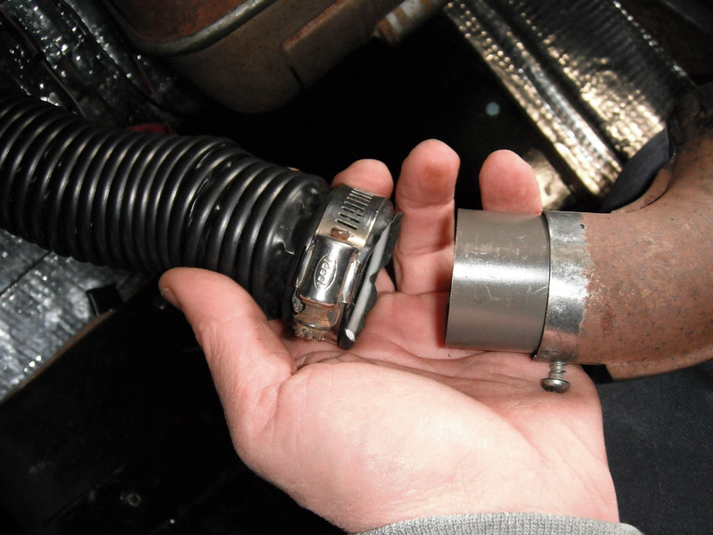 Now I could attach the hose to the collar in comfort, and then slide the collar into the heater box where a self tapping screw secures it in place.  Again, lesson learned. Sure hope I remember this on my next build. After finishing the vent hoses I finally got at the steering shaft. I have a history of taking precise measurements that later turn out to be wrong, so I’m very careful when I cut something that will cost me money if I screw up. The Double D steering shaft fit into this category, so I cut a ¾ inch strip of wood and hit the ends with a die grinder so that it would fit into the u-joints.  Once I tested it in place and was happy with the length, I made the cut on the steel DD shaft and installed it. With the column in its final position it was time to weld up the brake pedal. I had formed it to shape using the old “slice & dice” method, and I had to now weld up all them slices. I seriously need to invest in big oxy/acetylene tanks. I only have one of those mini kits, and it takes nothing to empty those tanks. 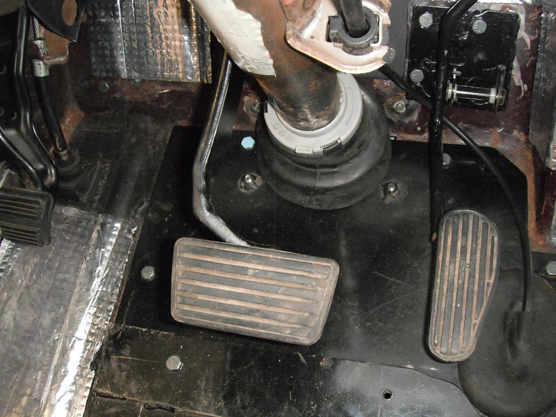 I am not all that thrilled with the sharp bends in the pedal (the slice & dice works nicer on thin stuff), so once I finally get a full size torch kit I will use the pedal from my parts Blazer to create something a little more elegant. With the brake pedal now welded up, my better half gave me a hand with bleeding the system. This went quite well, and it felt good at this point. Next I had some fun with a rear bumper. My Fargo didn’t come with one, and I needed something from that same era so I headed off to my local wrecking yard. It’s a funny comment on life out here in the sticks: my local yard has zero S10’s, but I was easily able to find a bumper from a 40’s era truck! I didn’t even have to unbolt it as it was sitting loose in the bed of a ‘43 Ford. I brought it home & fabbed up some brackets that I hope looked somewhat period correct:   Of course once you have a bumper, you’d be crazy not to put the tailgate on. The problem was that the tailgate hinges are on back-order, with absolutely no estimated time of arrival (like so many other things right now). They are however fairly simple things, so I quickly fabbed up a temporary pair that would allow me to have a tailgate until things get back to normal and stuff starts arriving. Here’s one of the temporary hinges:  And now I finally had a tail end that looked somewhat complete!   Next came a test fire to confirm some clearances between the steering column and the engine when the engine twists under acceleration. I checked the wires, hooked up the battery, hopped in and turned the key. It cranked, but wouldn’t fire. I also did not hear the fuel pump come on, so the debugging began. Zero fuel pressure and no sound from the pump. I debugged all the way to the pump, but of course the final connections to test are on top of the pump, squeezed in below the bed. Dropping the tank from below is something I hate doing, so instead I just removed the rear fenders and bedsides, and slipped the floor back 2 feet. Of course after I had done all this, a light bulb went off in my head. Remember that rear bumper I just installed? I had unhooked a ground that was in the way while doing that and forgot to reconnect it, and that was of course the fuel pump ground. I felt like a complete idiot at that point, but realized that this was an opportunity to do something useful. I had forgotten to slip some thin rubber pads between the bed and the frame mounts, so I did this now. I’m not sure how much they will help cut down noise and vibration as they are fairly thin, but it certainly won’t be worse than steel bolted to steel. Before any further running of the engine I installed a coolant overflow tank. Space is at a premium, so I used a small aluminum tank I got for 30 bucks on Amazon, after fabbing a bracket that tucked it into a little available corner (and yes, that horrible glow-in-the-dark orange hose it came with will be replaced with a black hose and routed properly!)  I now realized how close I was to being able to test this thing out. I have the hood and front fenders off to allow easy access to the engine. I spent a couple of hours checking bolt tightnesses, hose connections, fluid levels, wiring connections, etc etc etc, and then I was ready to fire it up and run it up to temp. I crossed my fingers and fired it up and let it run, while monitoring the coolant temp with a laser temp tester (I had reset the coolant temp gauge needle while fitting the S10 gauges into this truck so god only knows how accurate it is right now). I had to add a surprising amount of tranny fluid (I had lots puke out of the tailshaft while fooling around with the driveshaft), and had to top up other fluids as all the air worked its way out, but other than that it went well. The electric fan system kicked on automatically just as it should (thanks for the tech advice, Skymangs!) and the engine ran smooth and cool. Everything was going just fine until I looked up and saw a thin stream of green fluid squirting straight up about 4 feet into the air. The coolant overflow tank’s breather hole is tiny and on the top, so that excess juice shot straight up in the air. That tank only has a capacity of 800ml (less than a quart) and I guess the overflow as the system heated up was more than that. The stock S10 overflow tank has a far greater capacity so I’m not sure if I can continue using my spiffy new aluminum tank, or if I will have to find a place to mount a bigger tank. Other than that little hiccup, it went well. It starts instantly, idles smooth and responds crisply to throttle inputs. I decided that was a good point to quit while I was ahead. More to follow! |
|
|

|
|
|
#114 |
|
Senior Member
 Join Date: Sep 2017
Location: Bryan, Texas
Posts: 2,345
|
Re: Project Fargolet
Congratulations on the progress.
__________________
8man-aka Robert 1948 on a S10 Frame, small block with a carb 1954 Cab, 53 Front and Bed, 50 Doors, S10 Frame, Power TBD Build thread: "]http://67-72chevytrucks.com/vboard/showthread.php?t=746899&highlight=wife%27s+48[/URL] [/URL]http://67-72chevytrucks.com/vboard/showthread.php?t=840204 Last edited by 8man; 06-12-2021 at 08:49 AM. |
|
|

|
|
|
#115 |
|
Senior Member
 Join Date: May 2007
Location: Doodah Kansas
Posts: 7,774
|
Re: Project Fargolet
beauty work!
__________________
the mass of men live lives of quiet desperation if there is a problem, I can have it. new project WAYNE http://67-72chevytrucks.com/vboard/s...d.php?t=844393 |
|
|

|
|
|
#116 |
|
Registered User
Join Date: Sep 2018
Location: Ontario
Posts: 833
|
Re: Project Fargolet
Steering, Brakes, and Start up............ sounds like good progress.
I am glad to hear that I am not the only one to have to remove and reinstall items several times. (misery loves company I guess) Thanks for the update
__________________
https://67-72chevytrucks.com/vboard/...=797726&page=3http://https://67-72chevytrucks.com/...=797726&page=3 51 Chev 5 window on S10 with SBC 1958 Pontiac Wagon build https://67-72chevytrucks.com/vboard/...d.php?t=849781 |
|
|

|
|
|
#117 |
|
Registered User
Join Date: May 2009
Location: Grey County Ontario
Posts: 207
|
Re: Project Fargolet
Thanks for the encouraging words, and yes I believe I will do a video once it's trundling along with doors, fenders and a hood!
I spent some time cleaning up the shed and then doing a couple of little things. I was tired of looking at the shiny bolts and washers that hold the rear fenders to the bedsides and running boards, so I decided to crud ‘em up a little so that they blend in. First thing I needed to do was remove the coating on all that new hardware so that I could apply a rust accelerator. Over the years I have tried a number of things to remove coatings, and by far the best has been my hillbilly tumbler. Here’s a pic of the tumbler, and a pile of hardware after it has been through the process. The pile of untreated hardware to the right is in the pic just to show how nice a job this gizmo does: 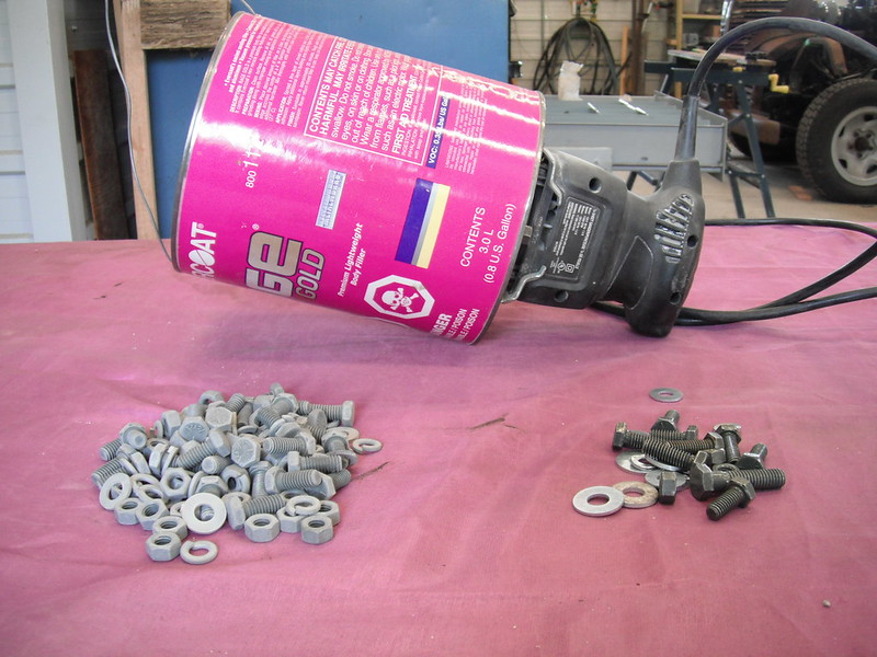 With the hardware down to bare metal, I could put it into the bath of hydrogen peroxide/vinegar/salt and let it sit until I liked what I saw. Next on my list were some reverse lights. These trucks did not come equipped with them, but it’s so dark here that they are really necessary. Because they never came with these trucks, I decided to mount them under the bed, far enough forward that they are not really noticeable in the daytime:  Next came the wiper motors. I had a pair of what I thought were good vacuum wipers, but now that I had a good running engine (with tons of vacuum) I discovered some issues. The passenger side wiper motor had a vacuum leak, and the driver side motor would only do a ½ sweep before locking up. I have been down this road before with vacuum wipers, and the last time I opted for a professional rebuild but still ended up with a system that was pretty crappy. With this in mind I ordered a new universal electric motor kit from Speedway, and I will see how easy it is to fab up something that looks presentable once I get it. If that works out I will order a 2nd kit. That’s it for now! |
|
|

|
|
|
#118 |
|
Registered User
Join Date: Sep 2018
Location: Ontario
Posts: 833
|
Re: Project Fargolet
as always, nice work.
Since my wiring harness had the reverse light wire I added 1 small LED in the middle to an already existing hole, subtle, but works. (look closely at the pic) also, your 'Hillbilly Tumbler", how did you attach the can to the palm sander? and do you use blasting media?
__________________
https://67-72chevytrucks.com/vboard/...=797726&page=3http://https://67-72chevytrucks.com/...=797726&page=3 51 Chev 5 window on S10 with SBC 1958 Pontiac Wagon build https://67-72chevytrucks.com/vboard/...d.php?t=849781 |
|
|

|
|
|
#119 |
|
Registered User
Join Date: May 2009
Location: Grey County Ontario
Posts: 207
|
Re: Project Fargolet
Tempest 67, regarding your reverse light: If by “subtle” you meant “invisible”, you are right. If you hadn’t told me exactly where it is I would have mistaken it for just another bolt!
As for the hillbilly tumbler, I had tried all kinds of ways to clean up small stuff like nuts, bolts, clips, small brackets, etc. and nothing works like this thing. I was even given one of those fancy “vibratory tumblers” once and there’s no comparison. Plus it’s easy to make and it costs next to nothing. Here’s the completed unit, hanging in place and ready to go:  The palm sander is just some cheapo unit I picked up at Canadian Tire for something like 15 bucks a while back. I simply drilled a couple of ¼ inch holes through the palm sander base, and bolted it to the bottom of an old gallon can. Here’s a bottom view:  And here’s a top view (looking down inside the can). I added a small plate in the can so that the bolts don’t chew up the thin metal that the can is made of:  You can also see some of my “media”. I have a tandem truck load of this stuff as I use it in the winter on my driveway. Any coarse sand will work, it makes no difference at all so just grab whatever is free! The load of parts in my previous post is about as much as I ever toss in, and it only takes an inch or so of sand in the bottom of the can to clean this many parts. After a load or two I change the sand as its effectiveness does plummet after a bit of use. One drawback to the hilly tumbler is that it is very loud. Hope this helps! |
|
|

|
|
|
#120 |
|
Registered User
Join Date: Sep 2018
Location: Ontario
Posts: 833
|
Re: Project Fargolet
Thanks for sharing the pics and the explanation, very creative of you..... I bet it is has a very irritating sound to it, but it looks like it works well.
There was a hole in the rear of the truck already, so I found a 'push in' LED light for $5 (Princess Auto) and figured I would give it a try. I will try to take a pic next time I am out at night....I also added a red LED in each bed rail and hooked it up to my 3rd brake light wire Can't wait to see your truck 'on the move'.
__________________
https://67-72chevytrucks.com/vboard/...=797726&page=3http://https://67-72chevytrucks.com/...=797726&page=3 51 Chev 5 window on S10 with SBC 1958 Pontiac Wagon build https://67-72chevytrucks.com/vboard/...d.php?t=849781 |
|
|

|
|
|
#121 |
|
Registered User
Join Date: Nov 2014
Location: somewhere, PA
Posts: 1,088
|
Re: Project Fargolet
awesome solution!
|
|
|

|
|
|
#122 |
|
Senior Member
 Join Date: May 2007
Location: Doodah Kansas
Posts: 7,774
|
Re: Project Fargolet
thats a great tech tip!
__________________
the mass of men live lives of quiet desperation if there is a problem, I can have it. new project WAYNE http://67-72chevytrucks.com/vboard/s...d.php?t=844393 |
|
|

|
|
|
#123 |
|
Registered User
Join Date: May 2009
Location: Grey County Ontario
Posts: 207
|
Re: Project Fargolet
My speedway wiper kit arrived, so I went to the shed and got to work. Most of these universal wipers have a 110 degree sweep. By making a template out of cardboard and playing with different sweep angles I had determined that 110 degrees would make for a difficult install on the driver side, and impossible on the passenger side (the sweeps on the 2 Fargo wipers are different from each other), but 90 degrees would be quite good. This led me to order the Speedway 90 degree wiper kit. I figured out how to mount both sides, fabbed up brackets, took lots of pics and then did a test. During the test, I lifted the arm so that the blade was above the glass (just in case something went wrong). It’s a good thing I did that. It was obvious that the sweep would have my blade smashing into the frame around the glass…….I stopped and reinstalled a cardboard template to see what was going on, and much to my surprise it turns out that the 90 degree wiper motor I bought provides a sweep of 110 degrees. Needless to say, I was perturbed. I fired off an email to the vendor (and they responded quickly and were good about it). I then started to hunt for a replacement motor that has a 90 degree sweep and a long enough shaft to work on the Fargo. The hunt is still on, and as I go through the various online universal wiper motors I am amazed at how many don’t provide a sweep angle (which is a rather crucial piece of information).
To cheer myself up, I stomped off to the shed to do something quick and instantly gratifying. I’d gotten tired of using the top of my skull to hold the hood up while tinkering underneath, so I fabbed up a pair of hood supports:   Next I decided to deal with the spare tire. The S10 mounting system would no longer work as the shortening of the frame would have the spare sticking out the back of the truck. I could have fabbed a mount further forward, but this is supposed to look as much as an original truck as possible, so the solution was simple. The Fargo came with a spare tire mounting bracket attached to the bedside so I just needed to make some simple mods. Here’s the original bracket. It still has the little pin to align the holes with the bolts (yup, bolts rather than studs, and the threads were opposite on the driver and passenger sides):  Making the Chevy wheel fit was just a matter of grinding off the alignment pin and drilling and tapping 3 holes on the Chevrolet bolt pattern. I could then use ½ inch bolts to affix the spare (these have a ¾ inch head, which fits the lug wrench for the S10 wheel nuts):  And here she sits now, with the spare in place: 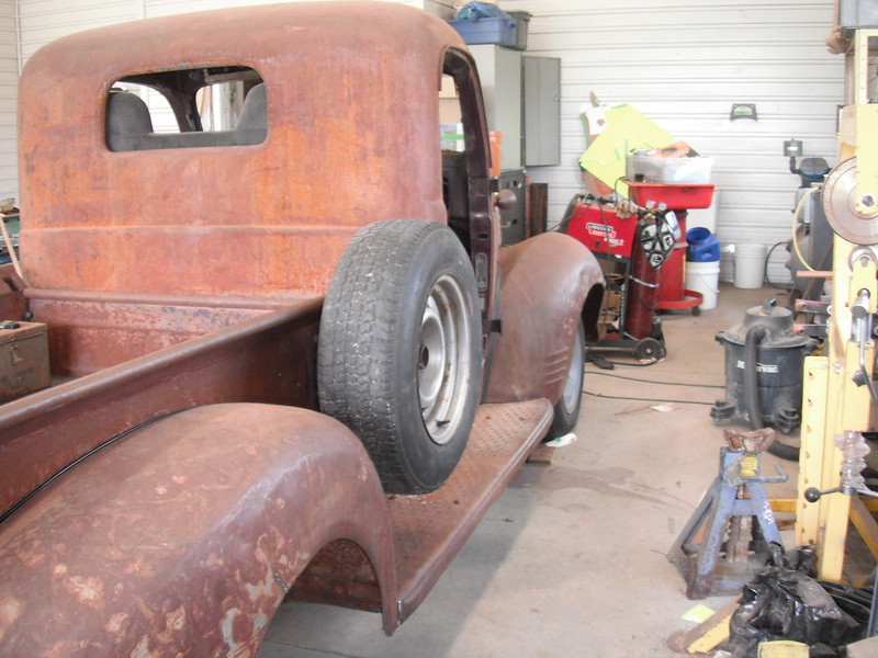 Hopefully I can sort out the wiper issue soon, and post how to replace the dual vacuum system with a cheap electric alternative. More to follow! |
|
|

|
|
|
#124 |
|
Registered User
Join Date: Jan 2014
Location: edgeley sask
Posts: 93
|
Re: Project Fargolet
This may be a pretty helpless comment, but. Are any rear window suv or minivan wipers more in the 90 degree range? Maybe a tractor cab wiper also?
|
|
|

|
|
|
#125 |
|
Registered User
Join Date: Nov 2014
Location: somewhere, PA
Posts: 1,088
|
Re: Project Fargolet
can you re-drill the pivot hole for the linkage? a shorter action arm may be able to reduce the sweet.
|
|
|

|
 |
| Bookmarks |
|
|