
 |
|
|
|
|
#1 |
|
Senior Enthusiast
Join Date: Feb 2007
Location: Spokane Valley, WA
Posts: 8,356
|
Re: Markeb01 Build Thread
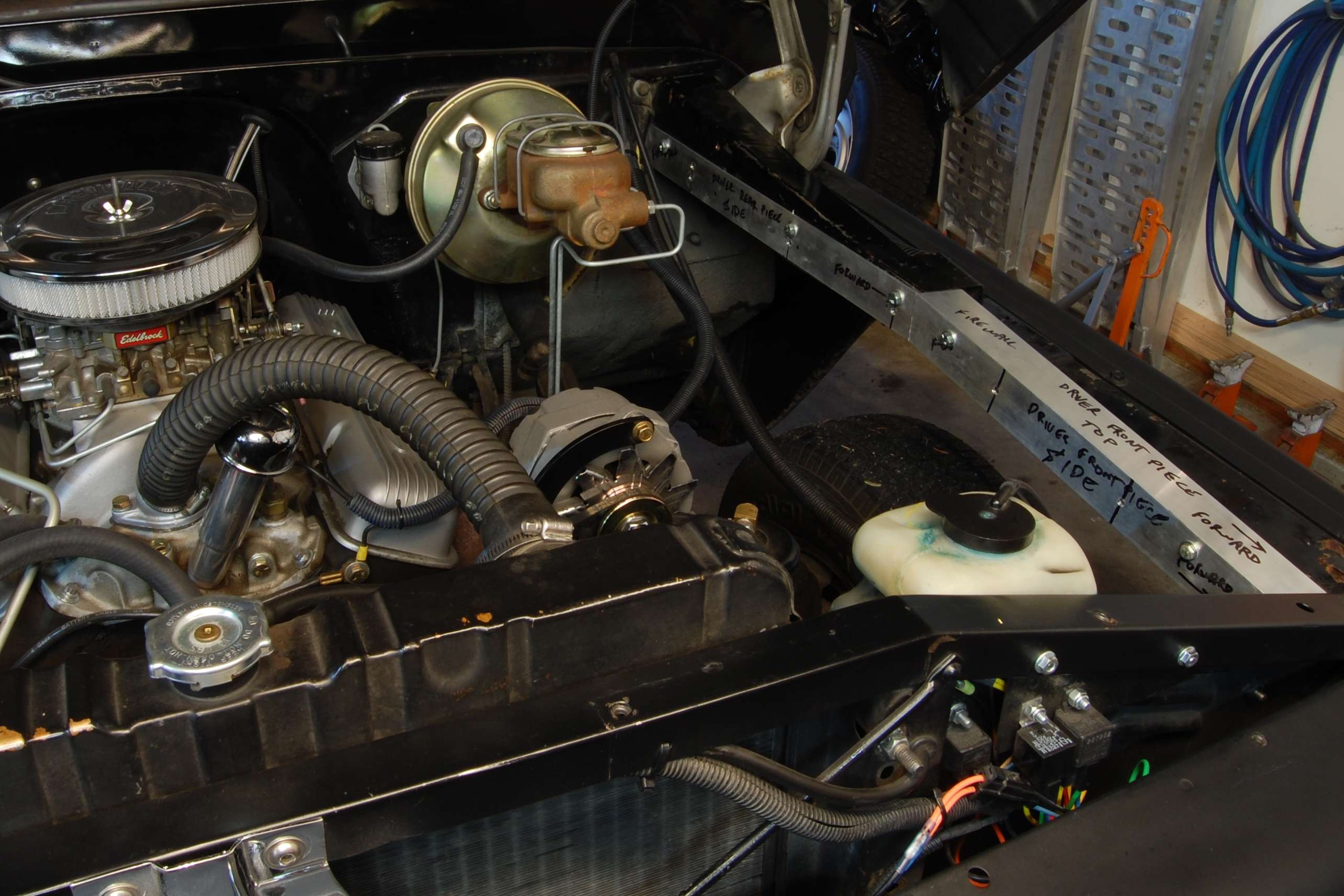
I wanted smooth edges covering all the rough sheet metal cuts, so aluminum angle was fitted the length of the inner panel cut line and attached with button head Allen screws. They were deliberately fitted in two pieces and with a bend in the middle to avoid being driven through the firewall into the occupants in the event of a crash.
  Rather than spending time finishing the repairs with body filler and labor, steel plates were fabricated to cover the repaired ledge portion between the hood springs and radiator support. 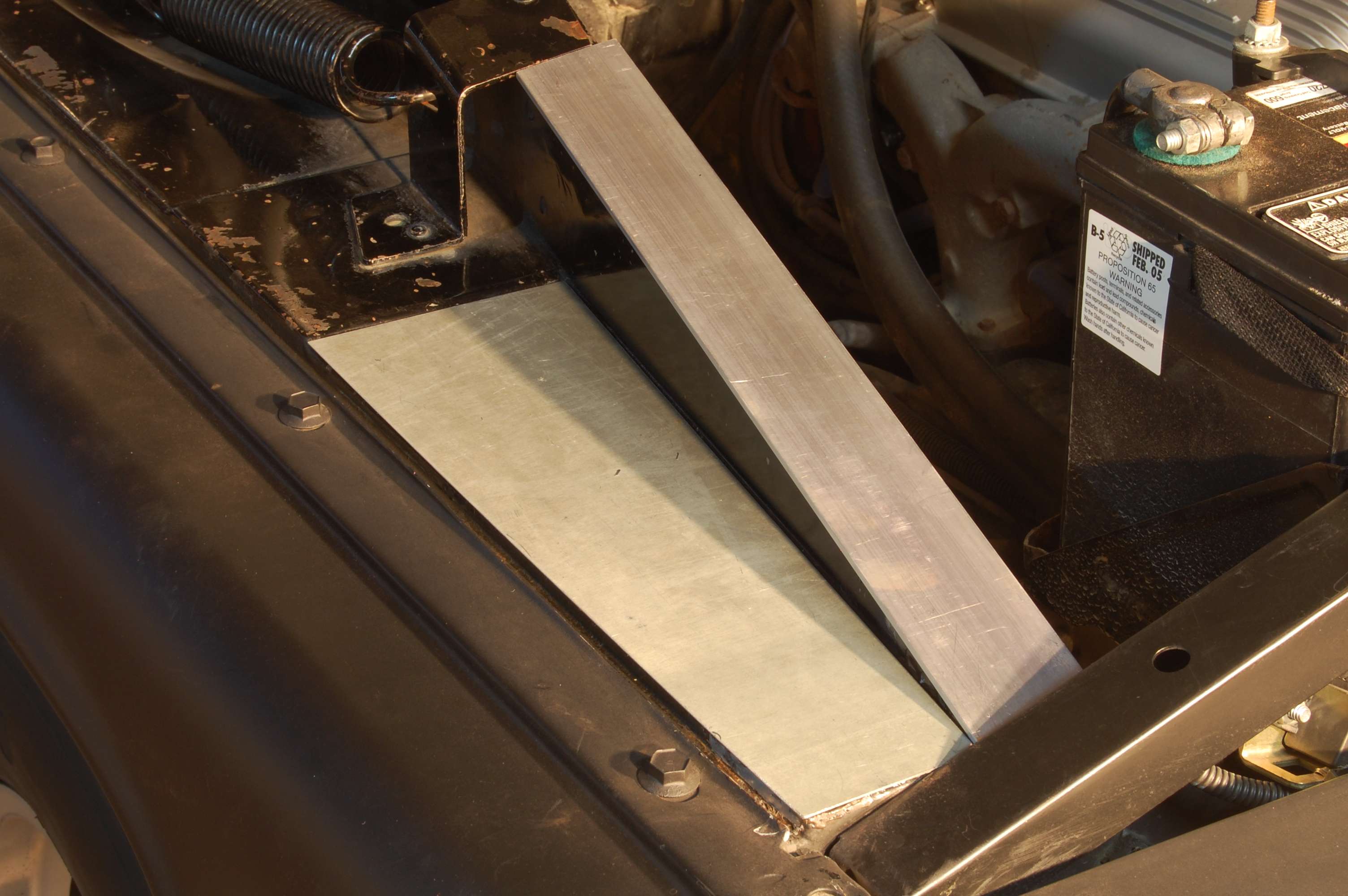 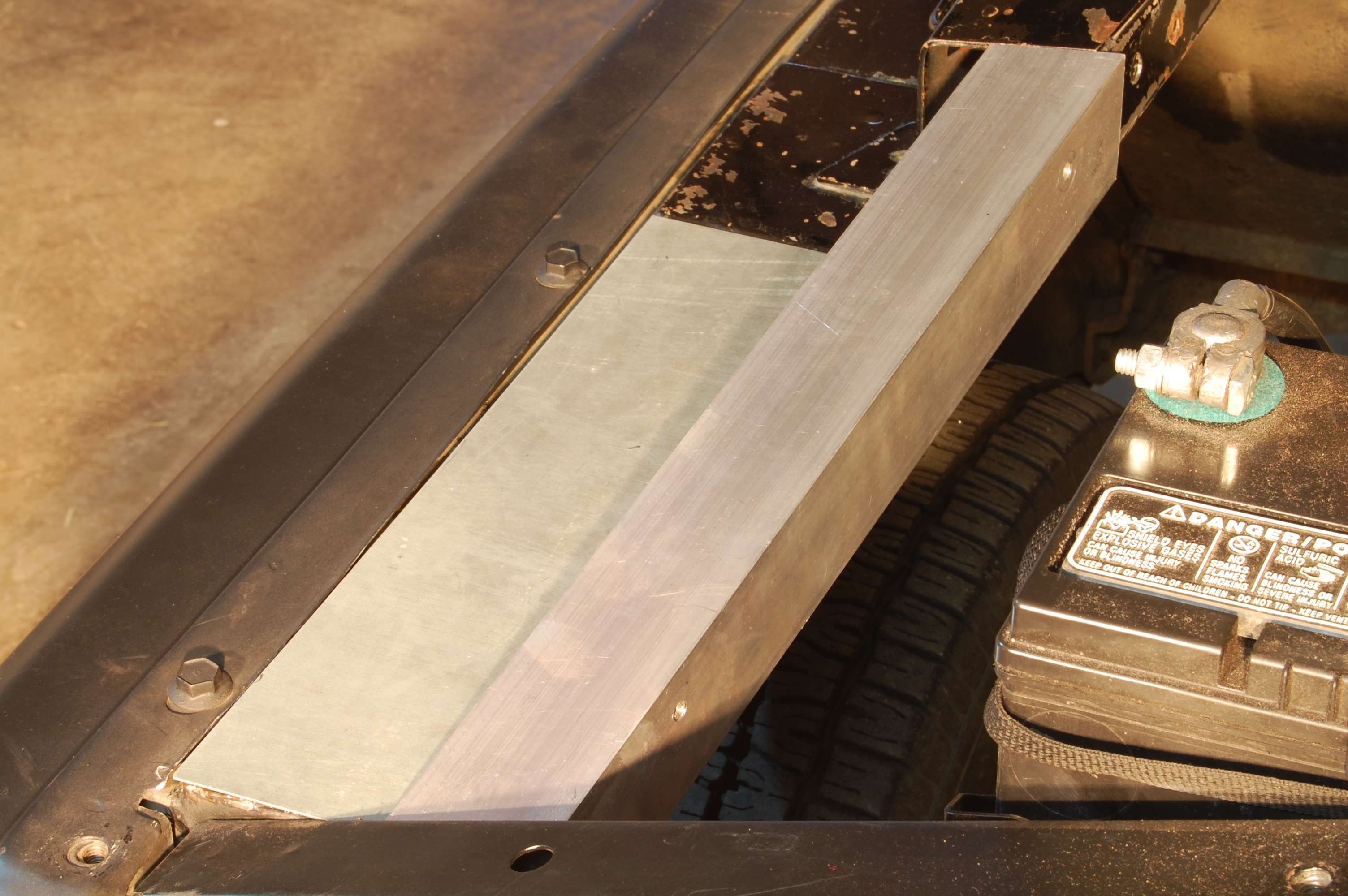 Once satisfied with the fit of all the plates and angles they were removed. The rusted areas over the reinforcement brackets were cut out, ground clean, acid washed, dams formed from steel brackets and duct tape, then filled with JB Weld. The gap in the angled portion was then filled with JB Kwik because it sets in 3 minutes (no picture). 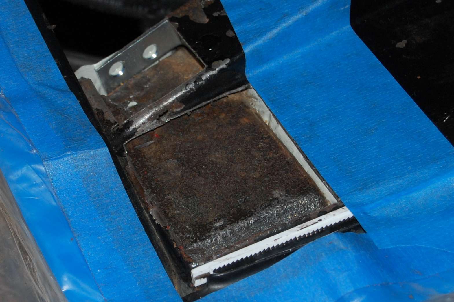 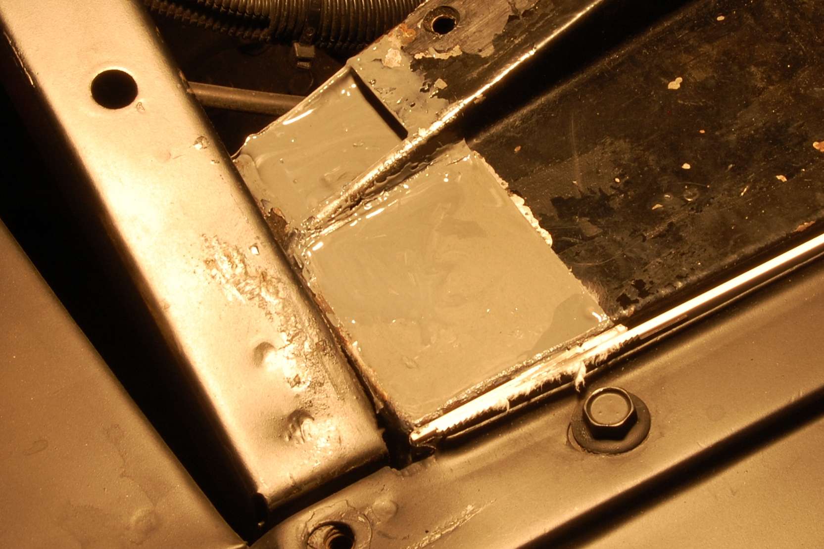 At this point all the new aluminum and steel parts were sanded down and brush painted with epoxy primer. The aluminum angles were bolted on and the steel plates were epoxied to the inner fenders with large C clamps over a generous bed of JB Weld. 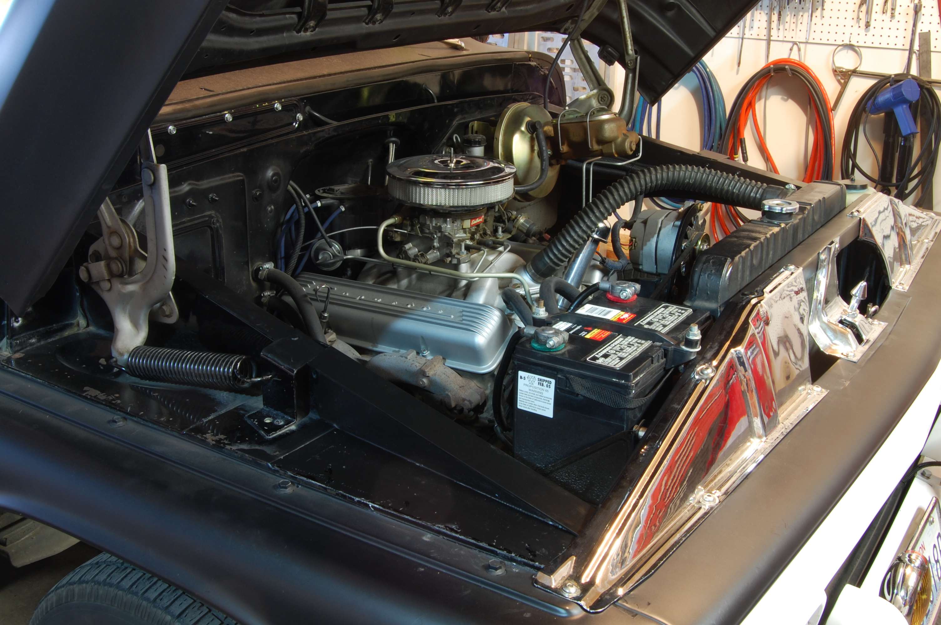 Before completing the engine compartment, two events occurred that convinced me to reinstall the Gaylord bed cover that had been leaning against the garage wall for the last two years. First, one of our dump loads managed to knock a dent in the back of the cab just above the front bed panel. Second, my brother in law sold us their old box trailer made out of the back half of an old Ford Courier, so I didnít need to abuse the GMC any longer. Because I had already installed the stainless bed rails, I first thought about buying a soft cover that fit between bed rails. But since I already had the hard cover, and considering how ridiculously expensive theyíve become it seemed more prudent to reinstall the one I already had. Problem being I didnít want to give up the bed rails. So after careful study, and against the advice of Gaylord, I decided to mount them on the hard cover purely for cosmetics. I couldnít use screws from the top because they would collide with the top of the bed sides. So I trimmed the cover seal underneath to accommodate stainless screws and fender washers from underneath pointing up. These were topped with chrome plated acorn nuts. I actually think they make a nice feature and look better than the original screws: 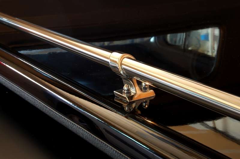 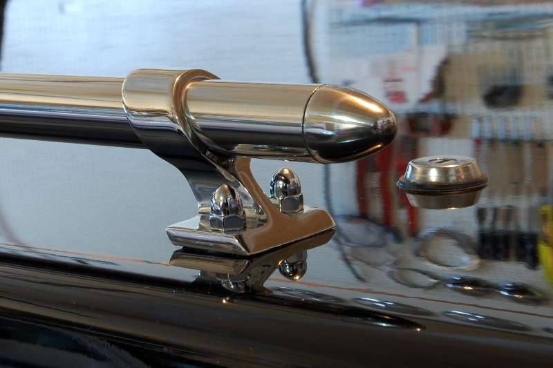 These were the first pictures taken after the cover and rails were reinstalled: 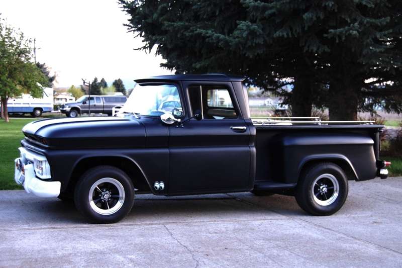 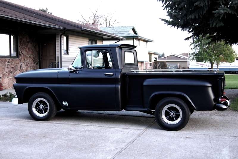
__________________
My Build Thread: http://67-72chevytrucks.com/vboard/s...d.php?t=444502 |
|
|

|
|
|
#2 |
|
Senior Enthusiast
Join Date: Feb 2007
Location: Spokane Valley, WA
Posts: 8,356
|
Re: Markeb01 Build Thread
With the bed cover in place it was right back to the engine compartment project. The final phase was getting all the prep done for an application of Raptor bedliner. With all the degreasing, sanding, grinding, filling, priming, and more sanding and more cleaning, this part of the project turned out to be every bit as much work as painting the whole truck.
First the hood, hinges, and springs were pulled:  A rented power washer blew off all the dirt and half the poorly prepped paint back to the original yellow on much of the outer firewall: 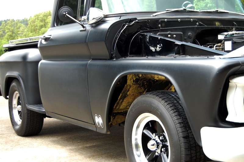 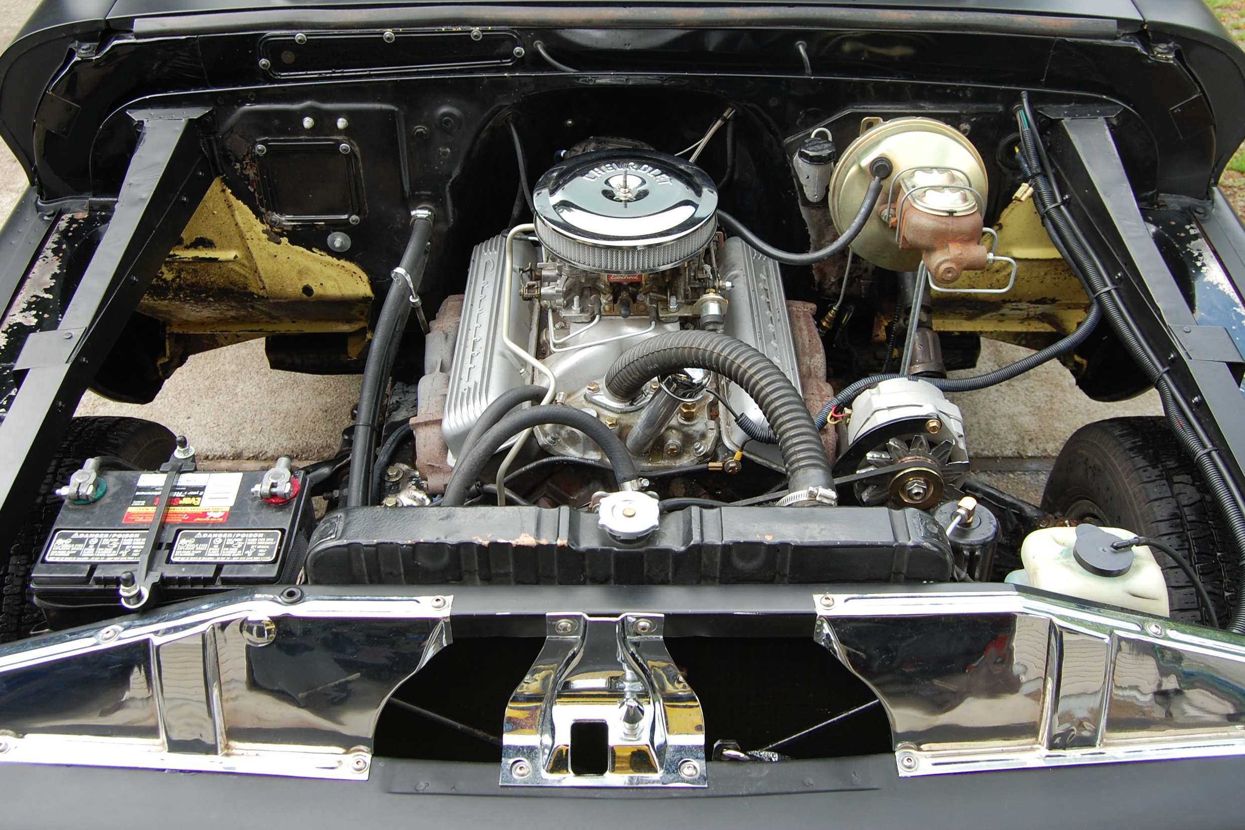 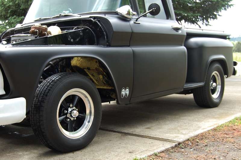 And this is just a shot of the truck with the hood off, showing how much light makes it to the pavement now: 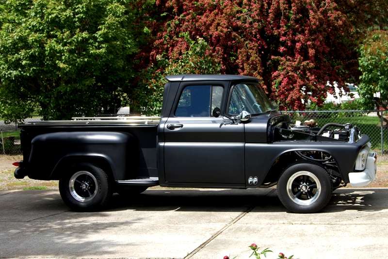 All of the removable panels were pulled for individual attention and fabrication of new gaskets: 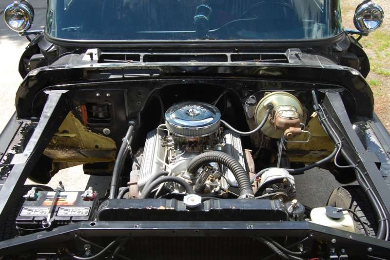 And a new hard line was formed for the clutch connection:  To replace this crappy looking version: 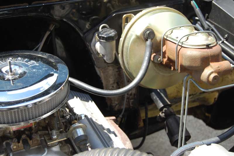 The new line in place: 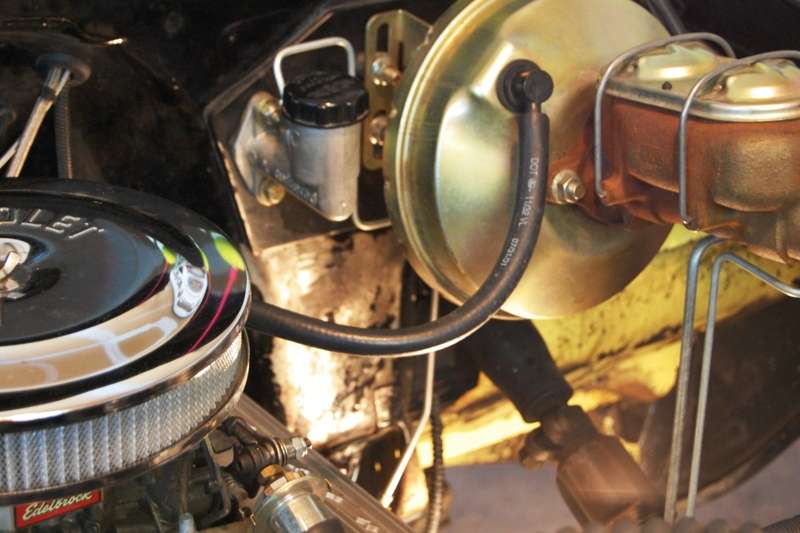 Not looking much different, this is after hours of sanding the heater panel openings, yellow portions of the firewall, and fender panels next to where the hood springs mount: 
__________________
My Build Thread: http://67-72chevytrucks.com/vboard/s...d.php?t=444502 Last edited by markeb01; 10-30-2012 at 12:34 AM. |
|
|

|
|
|
#3 |
|
Senior Enthusiast
Join Date: Feb 2007
Location: Spokane Valley, WA
Posts: 8,356
|
Re: Markeb01 Build Thread
My squeeze finishing up all the miserable prep I couldn’t reach:
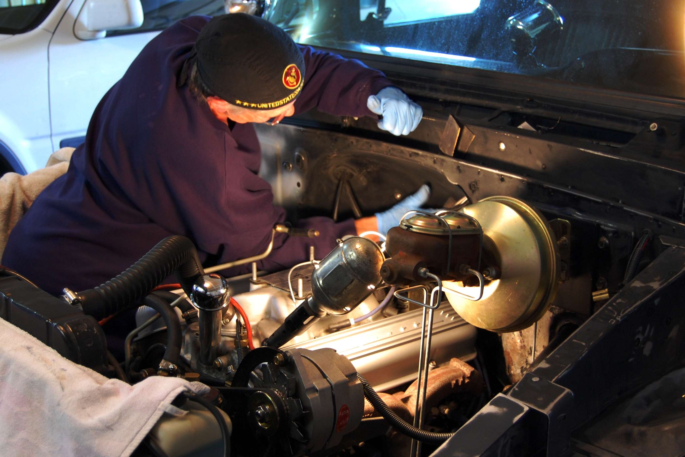 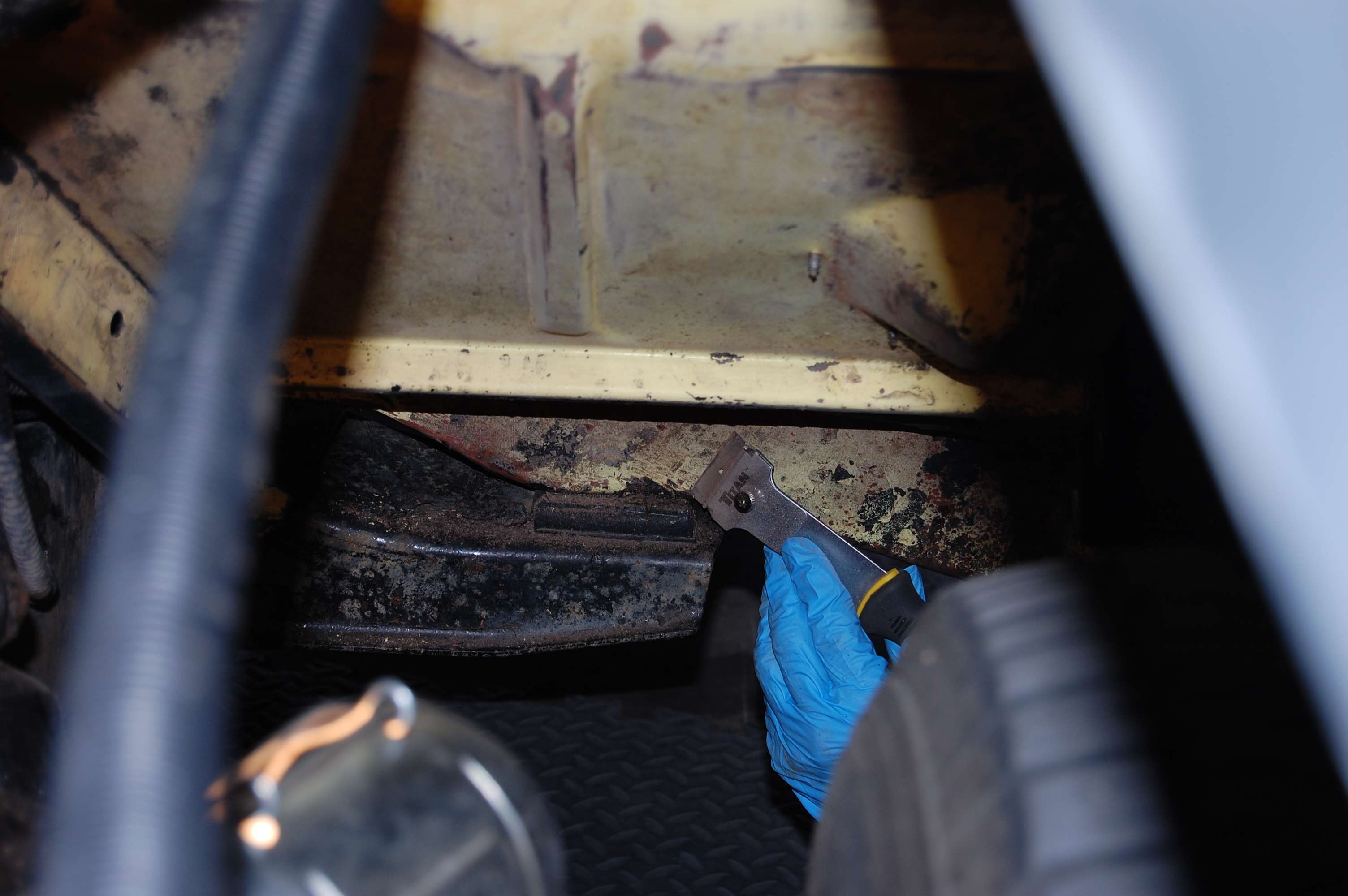 Here we are at final prep, ready to shoot the next morning:   Here are a few shots of the Raptor after most of the stuff was put back together: 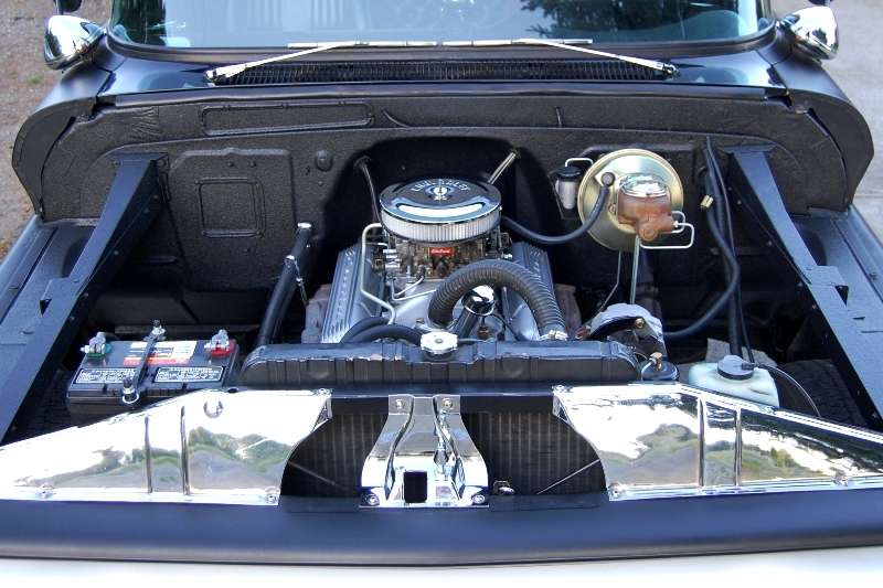   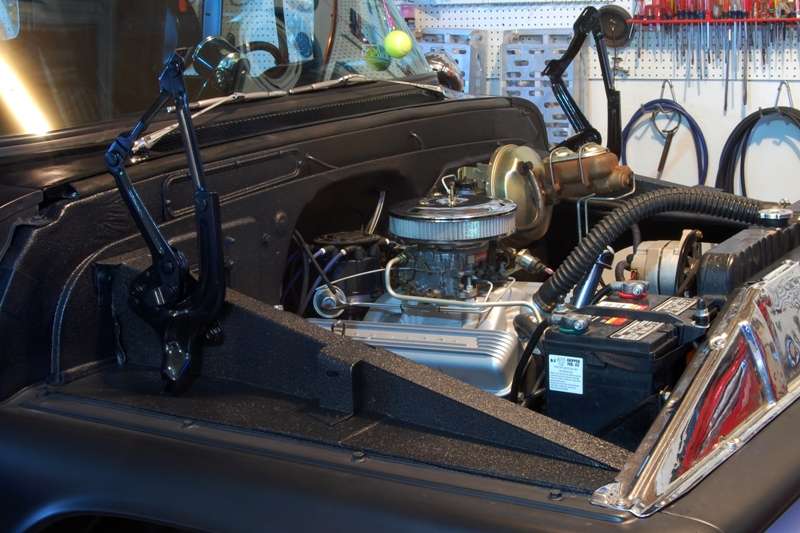 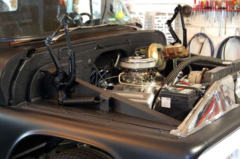
__________________
My Build Thread: http://67-72chevytrucks.com/vboard/s...d.php?t=444502 Last edited by markeb01; 10-30-2012 at 12:38 AM. |
|
|

|
|
|
#4 |
|
Senior Enthusiast
Join Date: Feb 2007
Location: Spokane Valley, WA
Posts: 8,356
|
Re: Markeb01 Build Thread
Hereís a simple method I came up with to reinstall the springs without scratching the paint. The first thing needed is a solid anchor to pull against. My ďclean benchĒ is bolted to the wall studs on two levels, and the bench is assembled with bolts, so I knew it was up to the task.
I clamped a piece of steel tubing to the spring support projecting forward a few feet in front of the truck to assist in lining the truck up with the bench leg (sorry no picture). I parked the truck aiming the tubing just inboard of the bench leg, so the spring would not be dragged against the anchor support on the fender panel. I hooked the spring to the hinge arm, and used an industrial S hook on the other end to provide more flexibility to the ratchet strap hook. The ratchet strap pulled the spring into position, and a squeeze clamp was used to press it into the slot and hold it in position. Since releasing the ratchet tension cannot be controlled, I simply drove the truck forward a couple of inches until the strap relaxed on the inner fender, and that was it. I also used this technique to remove the springs. And by pre-drilling front and rear alignment holes in the hinge mounting plates, they were reinstalled in exactly the same location using two 1/8Ē pilot bits. As a result no adjustment is required and there are no scars on the hinges or the mounting bolts. Iíve also installed the springs by mounting the front bolt and pivoting the hinge into position, but this seemed much easier with no risk of scratching the paint. 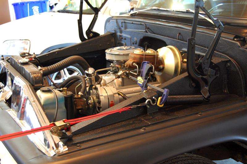 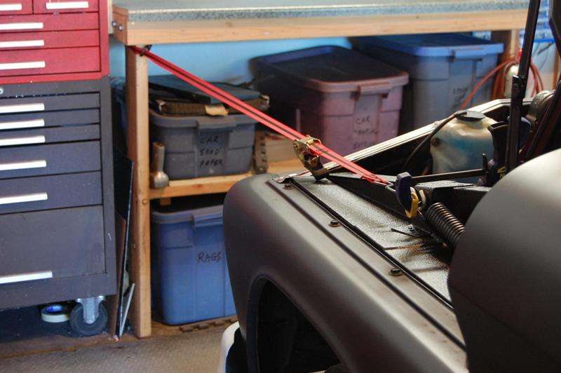 To put all this in perspective, once again this is what the engine compartment started out looking like: 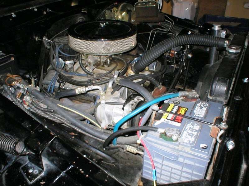
__________________
My Build Thread: http://67-72chevytrucks.com/vboard/s...d.php?t=444502 |
|
|

|
|
|
#5 |
|
Registered User
Join Date: Aug 2003
Location: tool box
Posts: 3,115
|
Re: Markeb01 Build Thread
fancy!
-W |
|
|

|
|
|
#6 |
|
Senior Enthusiast
Join Date: Feb 2007
Location: Spokane Valley, WA
Posts: 8,356
|
Re: Markeb01 Build Thread
I thought it might be a good idea to review this thread and see what I may have forgotten, and realized a few things.
1. My photo host site dropped about a half dozen pictures, which I uploaded again and have reinserted where needed. 2. I duplicated some stuff so those entries have been consolidated. 3. Some of the text has been edited for better accuracy or clarity. The last few projects were all completed late last year. I came to the realization that my heavy Simpson seat belt buckle was beating the crap out of my vintage Covico steering wheel (not that my delicate figure contributed in any way).  So two things were in order, new seat belts and attempted restoration of the wheel. I spent four and a half hours restoring the vinyl rim by hand. After nearly half a century of use it had plenty of nicks, scratches, and gouges. So two things were in order, new seat belts and attempted restoration of the wheel. I spent four and a half hours restoring the vinyl rim by hand. After nearly half a century of use it had plenty of nicks, scratches, and gouges.All the defects were wet sanded out with 400, 600, 1000, and 1500 grit paper. This was followed by 3 polishing steps with Semi-Chrome, and the final finish was brought back to original with 3 additional applications of Mothers Mag Wheel polish. The end result was worth all the elbow grease. Itís hard to photograph a shine, but Iím amazed how nice it turned out.  The accessory 3 gauge panel has been seen earlier, but it arrived during this period so Iíll provide more details here. When pulled from the package, it wasnít anywhere near the tip top shape I had hoped for. Unfortunately my son recently borrowed his buffer back so all the finish work had to be done by hand. So starting with 100 grit on an air file, I started tearing it up in order to get remove the deep scratches and get it back to flat. Final polishing came 3 Ĺ hours later. Hereís how it looked when first mounted with the VDO gauge in the center. The rims are so small they will fall through the hole if it's cut slightly oversize:  I never appreciated how puny and undersize the rims look on VDO gauges until I mounted the vacuum gauge in the same accessory panel with two Autometer gauges. The new Autometer vacuum gauge was installed a few minutes after it arrived. Both are 2 1/16" but comparing the two, the Autometer version is certainly more impressive (IMHO). The fun part being my wife inspired the upgrade. She insisted after all the work thatís gone into the project the gauges all need to match, so a new 160 mph Autometer speedometer replaced the VDO model as well. And this for comparison is the full Autometer set: 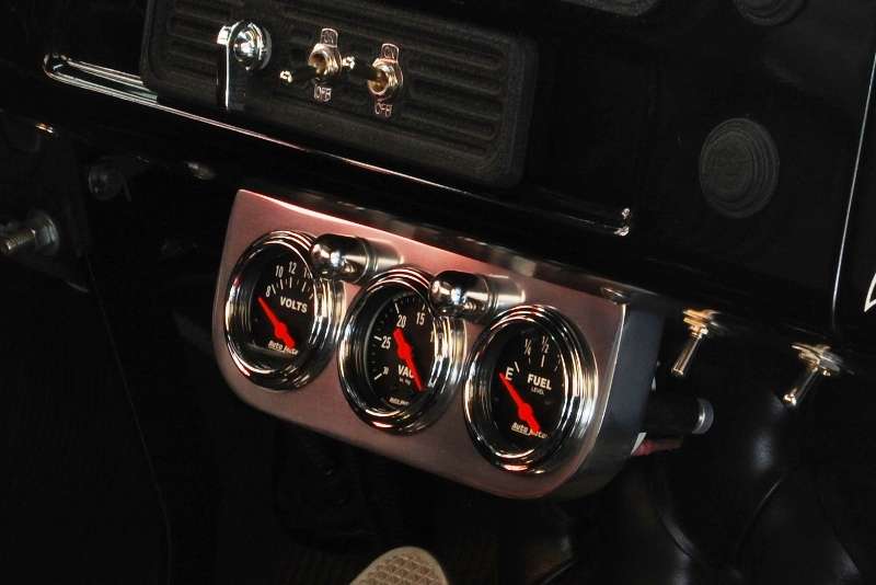 The modern design gauges in the panel do have internal lighting, but back when these external lighted panels were produced (around 1961-62?), many aftermarket gauges had no lights at all. The gauge housing was a simple solid metal can with two electrical posts sticking out the back, and nothing else. For a very brief period Moon, Dixco, and Eelco made panels for these unlighted gauges with the same dome shaped lights on the front which were suppose to illuminate the face of the gauge. In truth they mostly glared on the glass so you couldnít see the gauge reading anyway. In any event they aren't needed in my setup, I just always loved the way they looked and spent 10 years looking for this type panel at a price I could afford. The external lights are functional but not connected. I'm not sure if there's any advantage to hooking them up, so for now they remain unwired. Hereís what the panel looks like with the internal lights illuminated:  These panels went obsolete very quickly because the next generation of gauges came with plastic lined "translucentĒ windows around the perimeter of the gauge housing, just behind the rim. A sheet metal piece was attached to the back of the panel allowing a bulb to be plugged in, which sprayed light everywhere. Some of the light spilled into the gauge providing marginally improve illumination. Soon after, the next generation of gauges had a conventional tube attached to the back allowing a conventional bulb and socket to plug in, providing good lighting for the first time. While the gauge panel was being buttoned up, the new retractable lap belts showed up. After pretty extensive research I finally found an outfit that still made authentic belts with vintage chrome lift latch buckles, and the correct GM style tapered tongue with the square latch hole. http://www.cmwauto.com/MainMenu/Inte.../seatbelts.htm The problem being the buckle would still end up right in the middle, risking more damage to the steering wheel. So I went for the 70ís style with the starburst metal buckles on the side instead. It sure is nice not having the big heavy buckles and belts laying all over the floor. Light was pouring in through the garage door and the back window so the 2nd shot is pretty bleached out, but it shows how they mounted. 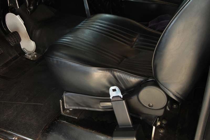 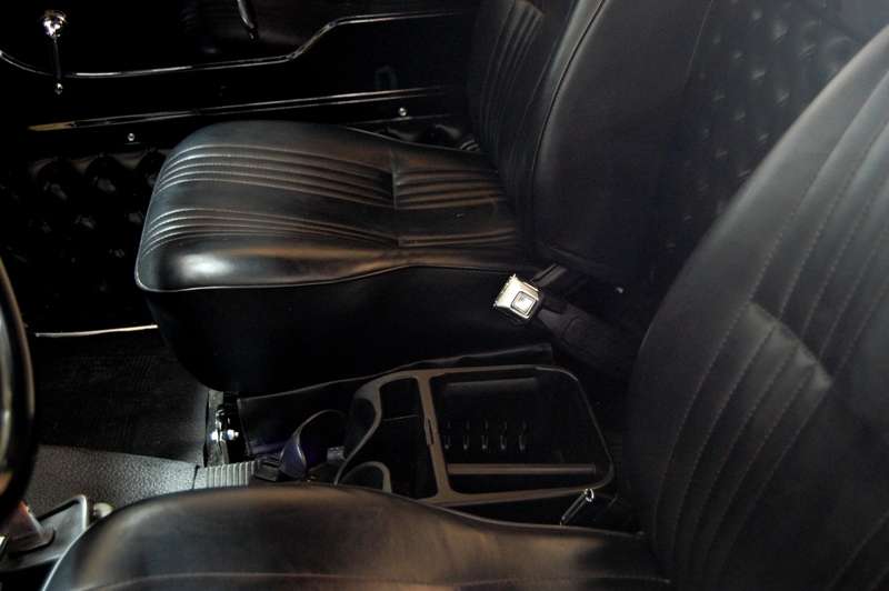 The 1960 GMC has a cover plate on the driver side over the area where the taillight wiring enters the cab. This required moving the retractor forward to the angled area. The anchor brackets needed a correction to the mounting angle. To avoid bending a curve into the bracket like happens when using a large Crescent wrench, I clamped the bracket in the bench vise and pried it open slightly with a crowbar, just enough to clear the bolt head I used next. Then I attached a heavy steel plate along with a stack of washers and a bushing that just fit inside my cheater pipe. I kept nudging it until the bracket measured straight up as mounted on the truck floor. Hereís the arrangement shown on one of the spare brackets that didnít need bending:   Rather than use the angle brackets on the inboard belts, I used the eye bolts that were in place for the Simpson belts. I just happened to have some serrated flange washers the same outside diameter as the eye bolts, making a simple and secure connection that didnít require crawling under the truck. Finishing the belt installation the new Autometer speedometer was installed and calibrated using road markers. Accuracy was double checked against our Honda. Although both gauges are the same size, the face and numbers on the Autometer are much larger and easier to see. Hereís the last remaining VDO gauge, the old speedo. The only nice feature it offered was thru dial lighting, but it looked washed out and the numbers were too small: 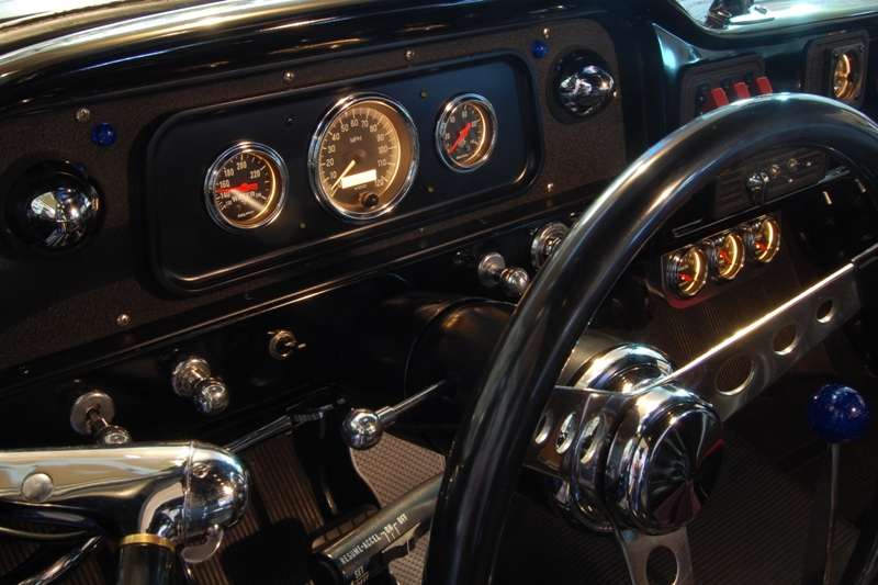 And hereís the new Autometer: 
__________________
My Build Thread: http://67-72chevytrucks.com/vboard/s...d.php?t=444502 |
|
|

|
|
|
#7 |
|
Senior Enthusiast
Join Date: Feb 2007
Location: Spokane Valley, WA
Posts: 8,356
|
Re: Markeb01 Build Thread
Outside Mirrors
I always had a passion for peep mirrors ever since I was a kid, probably because of their rarity and sense of impractical style. In the early 50’s not all that many cars had outside rear view mirrors. And the majority of cars that did have a mirror used the common straight arm accessory type that clamped on the front edge of the door. Very few cars used an overhead mirror, or what is now commonly referred to as a peep mirror. As a car nut kid that cared about this stuff, I probably saw less than half a dozen of both types of peep mirror throughout the 1950’s and 1960’s. The majority of those were the type that clamped on the rain deflector above the vent window found on cars up until about 1954. They looked like this: 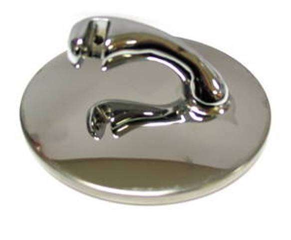 And here is a rather poor photo of how they mounted: 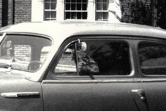 Although aftermarket peep mirrors are now as common as lug nuts, in the period before about the mid 1980’s when they started being reproduced, I only remember seeing two, and unbelievably at the same time in the same place. I was wandering through Mathis Auto Wreckers in San Leandro when I spotted not one, but two of these mirrors. The now common type clamped on top of a door was easy to snag, it came right off. The one on the vent deflector of a late 40’s Chevy coupe put up a real fight, and won. I just couldn’t get it off. I came back a week later with more tools but the car had been crushed. I’ve always been disappointed I couldn’t snag that one too, purely as a collectible. Here’s the one I did get, mounted on my 1950 Plymouth coupe. And for those that know the difference, yes I swapped over all the fenders, grille, and bumpers to make it look like a 1949: 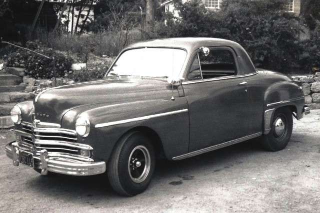 It lived on to serve duty on my last 54 Chevy: 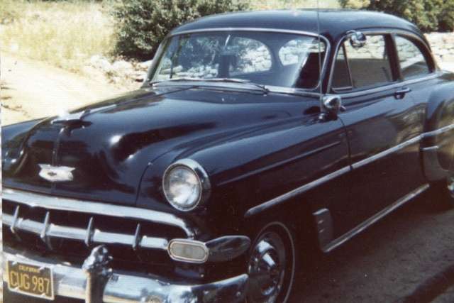 And later on my 46 Ford:  When the Ford was sold, I reinstalled the swan neck mirrors and kept the peep. It was mounted on the GMC for several months and worked fine (sorry no picture), but was replaced with a factory door mirror when one presented itself in the junk yard. If the factory hadn’t installed the permanent mounting nuts in the door, I would probably still be using the peep. I actually loved the view out of the mirror back then, because it was so close to my face I got a pretty good picture. Recently I tried installing it on my 1960 GMC again with the intention of mounting it permanently and pulling the factory door mirrors. Unfortunately I couldn't see doo doo. It was at night, and the mirror I have is an original Yankee with black beveled glass. It's nice for reducing glare, but may not be as user friendly as I remember it being, or maybe my eyes just aren't as young as they once were.  I threw in the towel and accepted I just couldn’t sacrifice the visibility offered by the factory mirrors, so they are going to stay. After spending so much time studying the mirrors, it became obvious they really needed a tune up. I never liked the stainless screws against the black arm, and the flat gaskets were shredded around the edges. The mirror heads were shiny black when purchased back in 1998, and long ago lost their luster Here’s a shot of the passenger side mirror when the spotlights were installed about a year and a half ago: 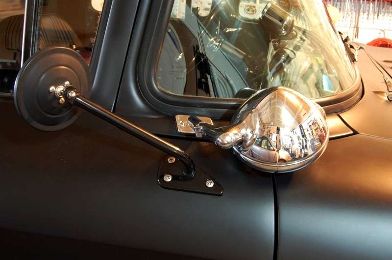 Off the truck, I took the opportunity to polish the back of the mirror heads. It took 6 different grits to remove the many years of oxidation. Here’s a shot of the finished driver side mirror on the right compared to the untouched passenger side.  And here’s a pic of the old flat passenger side gasket. It wasn’t really offering any protection to the paint, which now has gouges in it. Fortunately the new pad covered all the sins: 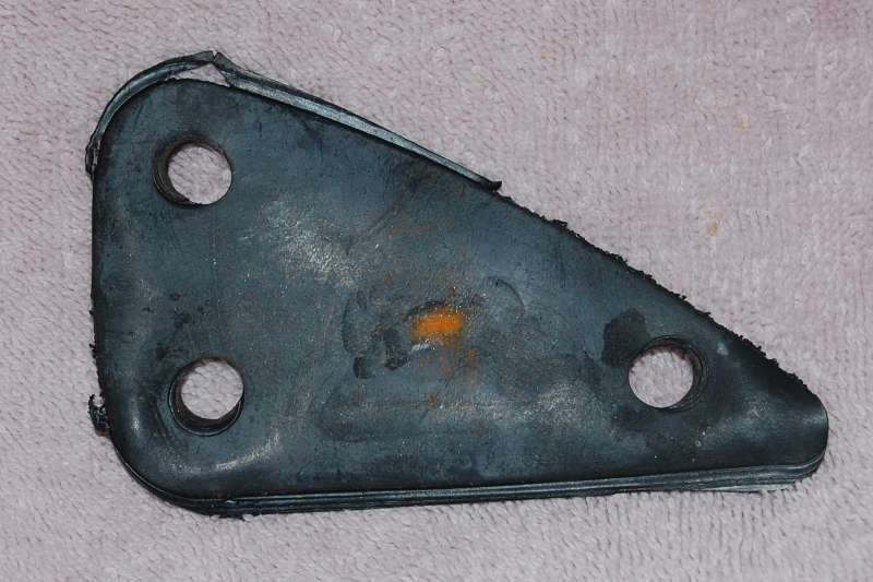 Here’s the new LMC molded mounting pad:  It’s a very nice part and makes the mirrors look much more finished on the truck. I’d seen them earlier on the Trucks TV show build up. The mounting pads do not disappoint, they are very high quality. I believe LMC is actually the company that produces these. I haven’t seen them available from anyone else. Here’s a link – part numbers 38-5806 and 38-5807: http://www.lmctruck.com/icatalog/cbe/full.aspx?Page=47 The mounting screws were hit with a stripper disc, coated with acid/etch primer and painted black. Here’s a shot of the finished effort. The picture isn’t all that great, but in real life the mirrors look like they belong now:  Fyi - I've read where a lot of customers are not very happy with LMC customer service. I’ve only purchased from them twice and both were good experiences. The other item was their clear dome light (36-4205 again available only from LMC). It’s a nice product that puts out about 10 times as much light as the factory lens, and I'm using the stock bulb. Since we actually use the truck at night it’s a nice upgrade: http://www.lmctruck.com/icatalog/cbe/full.aspx?Page=40 This wraps up the last project completed on the truck. Next up is polishing the newly acquired stainless windshield trim. If all goes well, and assuming I can find a functional windshield gasket, the trim will hopefully be on the truck this summer.
__________________
My Build Thread: http://67-72chevytrucks.com/vboard/s...d.php?t=444502 Last edited by markeb01; 05-12-2012 at 07:29 PM. |
|
|

|
|
|
#8 |
|
65 suburban vortec 5.3 bagged
Join Date: Jun 2005
Location: upstate new york
Posts: 1,317
|
Re: Markeb01 Build Thread
Nice work!!!
Posted via Mobile Device |
|
|

|
|
|
#9 |
|
Registered User
 Join Date: Mar 2012
Location: Shallow Lake Ontario,Canada
Posts: 201
|
Re: Markeb01 Build Thread
Thanks for the welcome to the forum, I think i will change my mind a few times before I get through the information here. Alot of great and different ideas here. I wish I would of found it last july. Enjoy
|
|
|

|
|
|
#10 |
|
Senior Enthusiast
Join Date: Feb 2007
Location: Spokane Valley, WA
Posts: 8,356
|
Re: Markeb01 Build Thread
I'm always glad to see new members having enough interest in these trucks to join up. I wish this forum was around when I started my build. There are so many different build styles available to help in selecting your preferences, and a wealth of experience available so everybody doesn't always have to learn the hard way.
__________________
My Build Thread: http://67-72chevytrucks.com/vboard/s...d.php?t=444502 |
|
|

|
|
|
#11 |
|
Registered User
Join Date: Sep 2011
Location: Tacoma, WA
Posts: 2,425
|
Re: Markeb01 Build Thread
 almost too much information. almost too much information.I either run across too many things I want to do to my truck, or I cannot remember where I saw something I decided later on that I liked !!! Great build Mark, and awesome info on it!
__________________
Michael McMurphy My 66 Stepside My 64 Tow Truck My 66 Tempest Table Of Contents Added to Page1 |
|
|

|
|
|
#12 |
|
Senior Enthusiast
Join Date: Feb 2007
Location: Spokane Valley, WA
Posts: 8,356
|
Re: Markeb01 Build Thread
The last few days have been spent researching and rereading all the information I could find on installing a 71-72 C10 cable operated throttle pedal on a 60-66, along with ordering various bits and pieces.
Part of me doesnít want to make the change at all. As a pre-teenager I grew up saturated with hot rod magazines showing Moon pedals in numerous rods and race cars. In my junior year in high school someone brought in a genuine Moon pedal to use as a casting pattern in metal shop. Disappointedly this was a senior class so I had to wait another year to attend. Just about every kid in the class ended up with a replica Moon pedal. Even if they didnít have a car, they had that pedal as a badge of distinction. Man I wanted one of those things. Unfortunately by my senior year there had been enough burn injuries that things changed and there were no more Moon pedals being cast. For many years I drove the GMC with the original gas pedal. It finally started looking pretty ratty so I installed an aftermarket replacement. Due to inferior materials, within a month or so the pedal was bent in about ĹĒ in the middle. So it seemed like a good time to go for a Moon pedal. My son gifted me a used original and it went right in the truck. It was not a good fit. The pedal was too tall and too wide for a truck with a high hump floor. I couldnít find a decent angle for it. It also had a tall heel cup and shoe traps on both sides. Stepping on the brake pedal brought my shoe down far enough to land on top of the left edge trap, accelerating the engine. Not cool. To make a long story short I kept trimming pieces off the pedal until it looked stupid and was ruined:  I ended up finding an original Cal Custom pedal on Ebay which fit and worked perfectly Ė almost. Iíve made numerous adjustments and improvement to the pedal including position/angle changes and adding a large block of Delrin to the back. I love the appearance, but Iíve never been able to achieve smooth-as-glass throttle operation. After years of improvements and annoyance, I decided it was time for another change. As of this morning it still looked like this:  I broke out the wrenches and so far the pedal has been removed along with the firewall pivot and all the linkage up to the carburetor. The carb stud for the cable connection has been installed, and the cruise connection has tentatively been reinstalled. The nutserts in the floor have been plugged with silicone sealant followed by a pair of 1/4x20 button head Allen screws. Tonight Iíll be drawing up plans for a block off plate for the firewall pivot so my son can machine one up. Not a whole lot to show at this stage so Iíll be posting pictures over the next few days as more parts arrive. As a side note I also got to enjoy the first time benefit of having removed the inner fenders. Missing 2 spinal discs and having 2 bad knees puts the 1960 pedal pivot from outside the engine compartment out of my reach. Even with the hood on it was relatively easy to climb into the passenger side of the engine compartment, stand on the floor, and reach over the engine to access the firewall. Iíve been modifying the truck to make it easier to work on for a long time, and Iím certainly enjoying it now.
__________________
My Build Thread: http://67-72chevytrucks.com/vboard/s...d.php?t=444502 |
|
|

|
|
|
#13 |
|
Senior Enthusiast
Join Date: Feb 2007
Location: Spokane Valley, WA
Posts: 8,356
|
Re: Markeb01 Build Thread
More progress today on the gas pedal project. Here’s a photo sequence showing what’s been achieved so far:
This was taken yesterday before anything was taken apart:  Today the pedal assembly showed up: 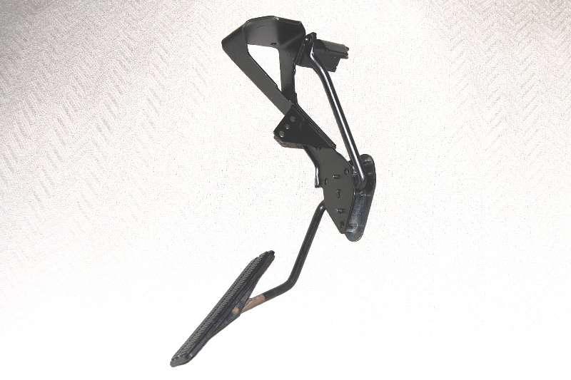 The upper chunk was quickly unbolted and the trusty Dremel tool was called on to slice off the attaching bracket, even with the top of the plastic firewall anchor: 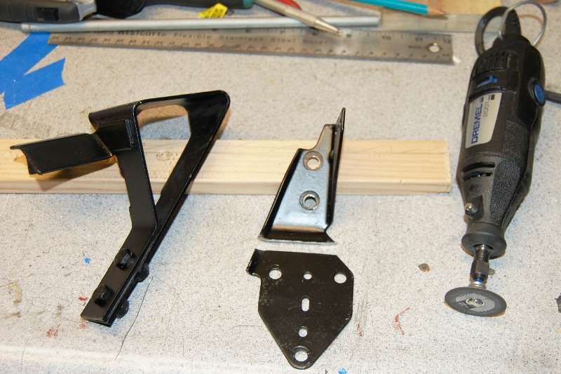 After further study I could find no reason to retain the ear on the upper left side, so it was sliced off and the remaining part angled to more closely match the other side:  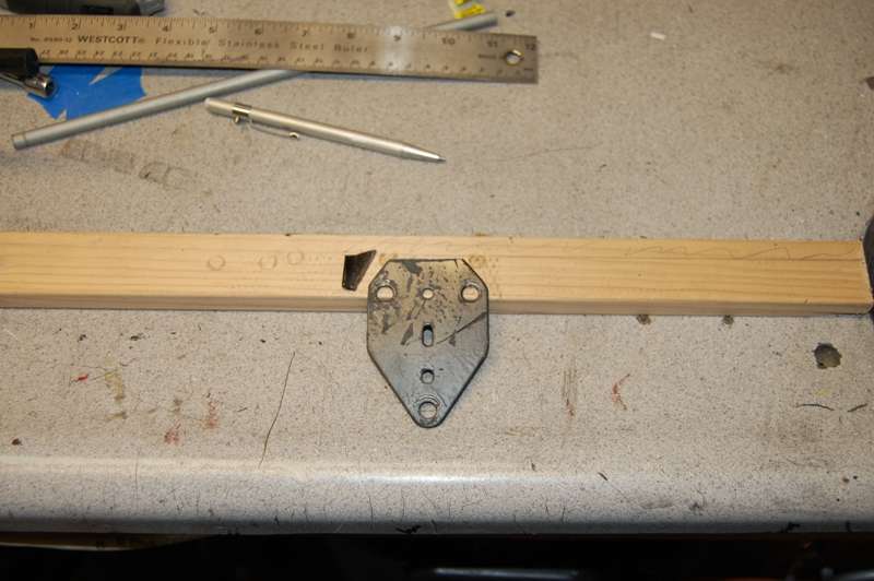 Early test fittings indicated the right side of the plastic mount should be ground flat to match the angle of the firewall. This picture is out of sequence because it shows all three mounting bolts, but it’s the only one showing where the plastic mount was modified: 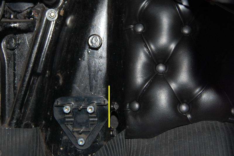 The complete assembly was test fit numerous times looking for the best fit at the firewall, the most comfortable pedal position, and level alignment. (Some of the pictures appear to lean to the left, but that’s because I didn’t have the camera level). Once the location was established, the upper right hole was marked with a 17/64 transfer punch (the next size up from ľ”). It was a tight slip fit to keep alignment accurate. That hole alone was drilled to ľ”, and the complete pedal assembly reattached to the firewall. This allowed a precise final alignment before marking the other two mounting holes. With the pedal where it belonged, the top of the bell crank needed to move about Ĺ” to the left. It was clamped in the bench vise at the point indicated by the arrow, and given a gentle nudge with an 18” adjustable wrench: 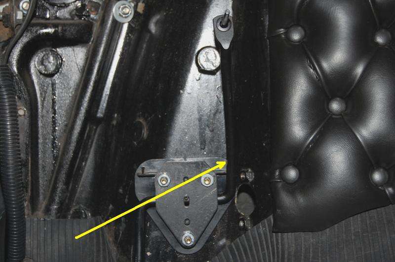 Bolted back in place, the upper cable hole was marked with a 5/32” transfer punch directly through the cable restraint bushing. And finally the cable hole was drilled out to Ĺ”.  Tomorrow I’ll get started filing the hole square. After cleaning up the garage, I headed over to dinner with my machinist son. He whipped up a block off plate the same thickness as the former pivot plate: 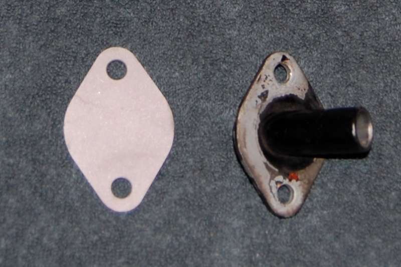 And as a final touch he glass bead blasted the parts to be painted. 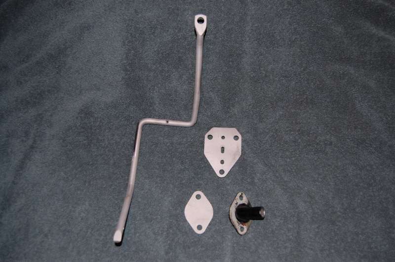 More to follow.
__________________
My Build Thread: http://67-72chevytrucks.com/vboard/s...d.php?t=444502 Last edited by markeb01; 04-01-2012 at 01:27 PM. |
|
|

|
|
|
#14 |
|
Registered User
Join Date: Sep 2011
Location: Tacoma, WA
Posts: 2,425
|
Re: Markeb01 Build Thread
This is an awesome detail for this mod Mark, as I will be installing that very same assembly!
Thanks
__________________
Michael McMurphy My 66 Stepside My 64 Tow Truck My 66 Tempest Table Of Contents Added to Page1 |
|
|

|
|
|
#15 |
|
Senior Enthusiast
Join Date: Feb 2007
Location: Spokane Valley, WA
Posts: 8,356
|
Re: Markeb01 Build Thread
I hope it proves helpful as this seems to be a very popular swap with very little information available outside the 67-72 community.
I’m taking a lunch break at the moment. This morning I scrubbed down the bead blasted parts with wax and grease remover, and shot them with U-Pol Acid/Etch primer. While the primer was drying I used steel wool and WD40 to clean up the retaining pin and spring that hold the pedal to the bell crank. After about 30 minutes dry time under the heat lamps I followed up with 3 coats of Martin Senour 7239 Gloss Black I picked up at Napa Auto. This isn’t a very good picture, but the parts look great in real life. . With the parts cooking under the lamps I got started on squaring up the cable mounting hole in the firewall.  The help insure the cable hole came out square and level, I started out by making a template/guide. I applied a length of 2” masking tape to one of my wife’s cutting boards. A Ĺ” square was marked and cut out freehand with an Xacto knife.  It was lined up and stuck over the 1/2” hole: 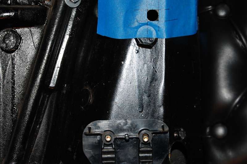 There was less to remove than I expected, and the corners were filed out quickly. It occurred to me I have a 400 grit stone in my stash, so I checked and sure enough it is exactly Ĺ” square. It was used for a go/no go gauge until it slipped through. Now I have a nice 400 grit polish on the edges of the opening. 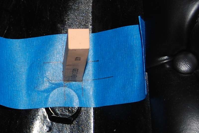 After lunch I’ll reassemble the pedal assembly and connect the cable. The only hold up now is waiting for the carburetor anchor bracket to arrive. It should be here today or tomorrow. Back to work!
__________________
My Build Thread: http://67-72chevytrucks.com/vboard/s...d.php?t=444502 Last edited by markeb01; 04-01-2012 at 01:37 PM. |
|
|

|
|
|
#16 |
|
Registered User
Join Date: Sep 2011
Location: Tacoma, WA
Posts: 2,425
|
Re: Markeb01 Build Thread
I got my set up off the '85 Sierra that I took the motor out of, so when I do all this I will just be marrying those two back up.
Now that I got the gas pedal area of my floor done, I was kicking around the idea of doing this mod. I am on the fence about it because the motor is not mounted yet, and I dont want to goof this up on distances by mounting the pedal without having the engine in as a reference. You have my undivided attention at this moment though !! LOL
__________________
Michael McMurphy My 66 Stepside My 64 Tow Truck My 66 Tempest Table Of Contents Added to Page1 |
|
|

|
|
|
#17 | |
|
Senior Enthusiast
Join Date: Feb 2007
Location: Spokane Valley, WA
Posts: 8,356
|
Re: Markeb01 Build Thread
Quote:
__________________
My Build Thread: http://67-72chevytrucks.com/vboard/s...d.php?t=444502 |
|
|
|

|
|
|
#18 |
|
Registered User
Join Date: Jun 2010
Location: gadsden, alabama
Posts: 468
|
Re: Markeb01 Build Thread
is that a quarter and nickle stuck to your firewall or an illusion ? or my bad eyesight
__________________
Due to financial constraints, the light at the end of the tunnel will be shut off until further notice |
|
|

|
|
|
#19 | |
|
Senior Enthusiast
Join Date: Feb 2007
Location: Spokane Valley, WA
Posts: 8,356
|
Re: Markeb01 Build Thread
Quote:
http://67-72chevytrucks.com/vboard/s...highlight=weld
__________________
My Build Thread: http://67-72chevytrucks.com/vboard/s...d.php?t=444502 |
|
|
|

|
|
|
#20 |
|
Senior Enthusiast
Join Date: Feb 2007
Location: Spokane Valley, WA
Posts: 8,356
|
Re: Markeb01 Build Thread
After vacuuming up the last of the mess the cable was slipped in place and the pedal assembly installed. The cable remained loose until the carb connections were complete to allow for best routing.
Here’s a shot of the finished install from the driver’s seat after everything was connected. The gas pedal is just about centered half way between the brake pedal and the transmission hump. I don’t really want the eye drawn to the shiny silver mounting nuts so I’m going to etch prime and paint them gloss black:  Here are before and after shots from the passenger side: 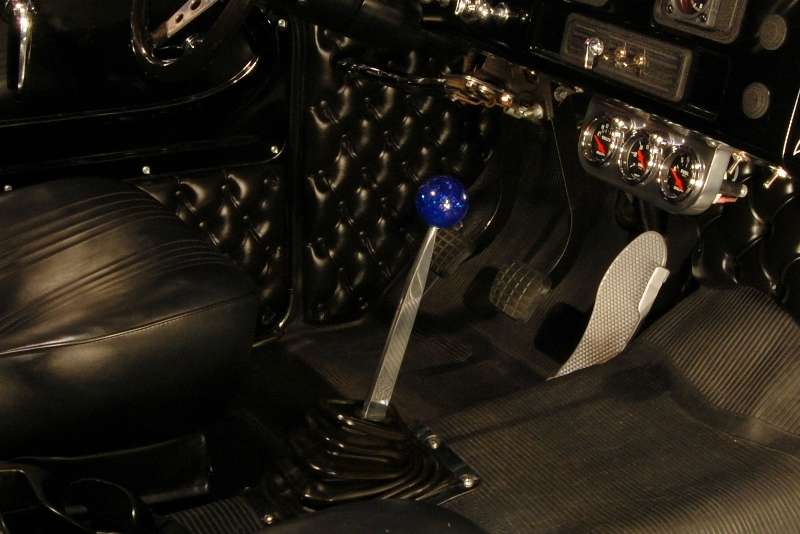 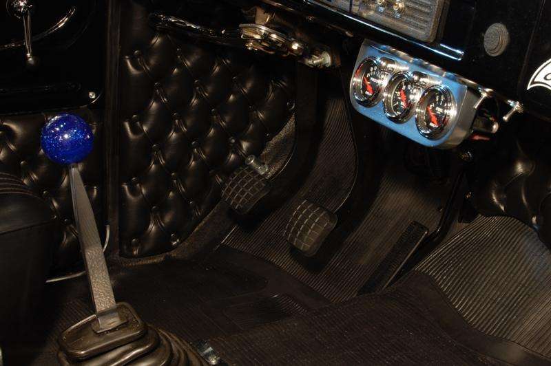 Compared to the aluminum pedal the never version is certainly unimportant looking, but it does work much better. It’s very smooth, provides a more precise response from the engine than the old setup, and allows a more natural positioning of the foot. The interior changes from start to finish took longer to write up and take pictures of than it did to perform the actual modifications. Compressed into actual working time it probably took less than a couple of hours to do the whole thing. The carburetor bracket and the Chevelle disc brake pad showed up at the same time, so I took a quick look to see it I could slip the pad on before moving to the engine. Not a chance. While it looks similar to the 71-72 pad, it is unfortunately about a ĺ scale version. To use it would require cutting at least ľ” off all four sides of the steel support and that’s more work than it’s worth to me. I may still pull the emblem however and install that on the 71-72 brake pedal pad, unless I go with the stainless trim designed for the 71-72 pedals. 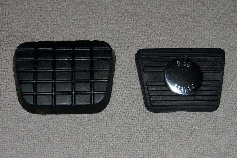 The pad I picked did in fact turn out to be an exact duplicate of the OEM version. The emblem curvature, shine, and printing are perfect. Post #12 on the following link shows the quality of the others I had to choose from: http://67-72chevytrucks.com/vboard/s...d.php?t=516373 I’m going to be adding new 71-72 brake and clutch pedal pads, but I’m not sure about the stainless trim. Opinions are welcome on whether the 71-72 trim would be an improvement or not on all three pedals. Next up, the engine connections.
__________________
My Build Thread: http://67-72chevytrucks.com/vboard/s...d.php?t=444502 Last edited by markeb01; 03-30-2012 at 04:44 PM. |
|
|

|
|
|
#21 |
|
Just here to tinker
 Join Date: Jun 2008
Location: Holland, MI
Posts: 3,697
|
Re: Markeb01 Build Thread
Hey Mark, I think the stainless trim would be nice to break up all the black down there. The install looks really clean and sharp, just like all the rest of your work.
__________________
78 C10 SWB Diesel #1 (wrecked)http://67-72chevytrucks.com/vboard/s...1978+silverado 78 C10 SWB Diesel #2 (sold)http://67-72chevytrucks.com/vboard/s...d.php?t=650751 60 GMC Suburban (sold)http://67-72chevytrucks.com/vboard/s...d.php?t=445526 60 GMC 1000 (sold)http://67-72chevytrucks.com/vboard/showthread.php?t=298235 67 GMC 1500 (sold) http://67-72chevytrucks.com/vboard/s...d.php?t=803695 73 Chevy C20(Daily)http://67-72chevytrucks.com/vboard/s...d.php?t=852767 86 Suburban(summer unit) http://67-72chevytrucks.com/vboard/s...d.php?t=810697 88 Suburban 4x4(sold) |
|
|

|
|
|
#22 |
|
Registered User
Join Date: Jul 2005
Location: Spanaway, WA
Posts: 103
|
Re: Markeb01 Build Thread
Your build is proof a truck is never finished, one of my favorite trucks around. About your pedals I like the look of the trim without the disc brake badge, and disc brake badge without the trim. The pedals do look really plain though all black.
Posted via Mobile Device |
|
|

|
|
|
#23 |
|
Senior Enthusiast
Join Date: Feb 2007
Location: Spokane Valley, WA
Posts: 8,356
|
Re: Markeb01 Build Thread
Thanks for the comments guys. It’s funny I was teasing my wife the other day about buying another old project truck. Her response – “Why, you can’t finish the one you’ve got”! Zing!
I didn’t have a bracket available to mount the forward end of the throttle cable. I looked through everything Edelbrock had to offer and didn’t find anything that looked suitable. A couple more hours of internet searching turned up this Holley/GM bracket. Holley part number 20-44: 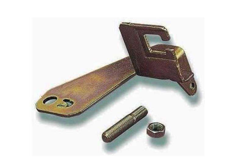 Of course like most street rod parts it couldn’t be installed without modification. My Edelbrock carb is mounted on the 4 outboard mounting studs which wouldn’t work because of the anti-rotation tab over the outboard mounting hole in the bracket. No problem. I pulled the carb expecting to add a second stud into the inboard mounting hole. Imagine my enthusiasm when I got the carb off and realized the Performer RPM manifold I’m running only has the outboard holes! Here’s the normal Performer intake mounting flange with 8 stud holes: 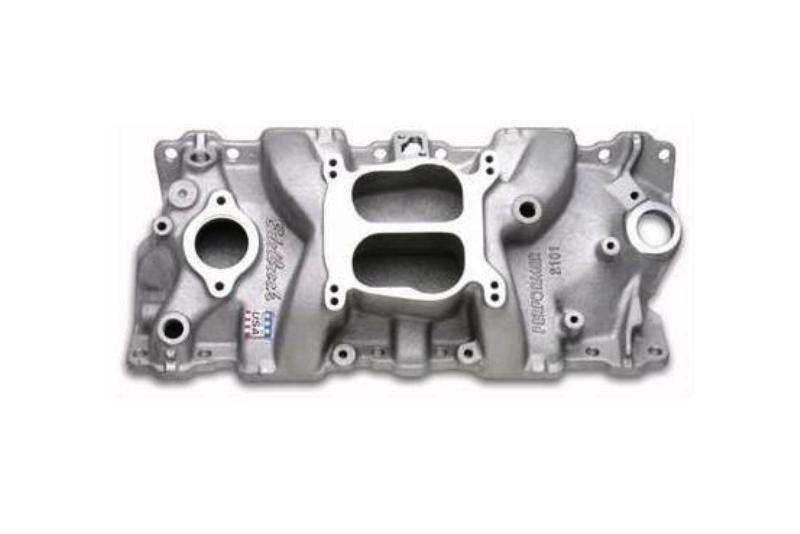 And here’s the RPM version I have: 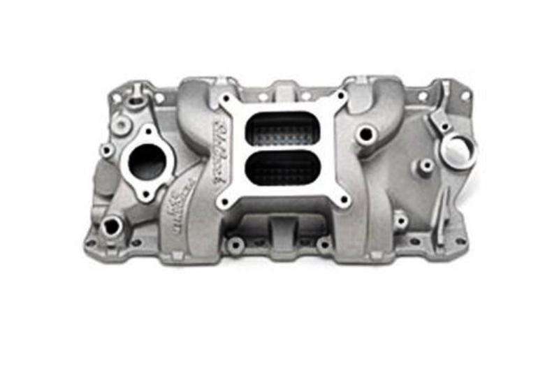 Back in the house for more another search, and another hour wasted not finding anything better. More time spent trying alternate orientations I ended up back where I started. The final solution was to flatten the anti-rotation tab and drill the outboard hole in the Holley bracket. But I still needed something to keep it from rotating under pressure. Years ago I installed an Edelbrock bracket kit (350-8036) for my Turbo 350 kick down linkage: 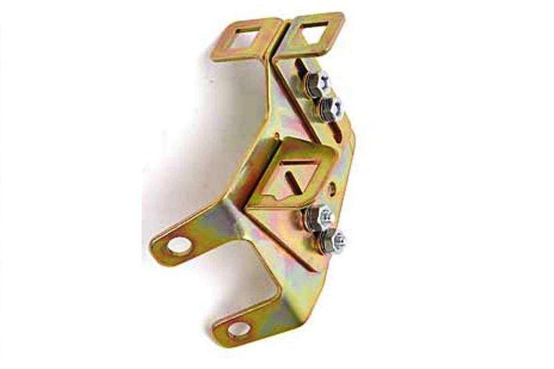 Currently the main bracket is bolted to the intake manifold and the upper left square attachment is used for the cruise control. A simple solution was to add a small plate between the cable bracket and the kick down bracket providing a solid anchor. Subsequently I discovered Holley part number 20-88 which would have bolted to the outboard stud and saved me at least 2 hours of freezing my ass off in the garage sorting all this out. 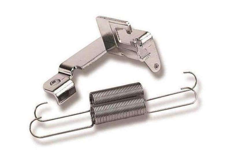 As a side note the Holley 20-44 bracket has the worst gold cadmium finish I’ve ever seen. It’s swirly black instead of gold colored. At first I thought it was a customer return with grease all over it, but it was just a horrible plating job. Because I wanted the truck back on the road it got used regardless of the appearance. Final notes - the standard 1972 350 cable is actually several inches too long for my application requiring a pretty severe corkscrew routing between the firewall and the carburetor. Apparently my engine is closer to the firewall than a stock 71-72 C10. The 4x4 version is shorter, but I don’t know by how much. It might have been a more suitable choice, but OEM versions are claimed to no longer be available. In order to keep the cable level with the throttle linkage I added an Adel clamp to the kick down bracket which also removed any strain from the factory cable/bracket attaching grommet. Installing the cable grommet into the square bracket hole was a nightmare. If I ever have to do it again I will modify the bracket first, angling the square entrance slot to more closely resemble the factory GM approach as shown on this Monte Carlo bracket: 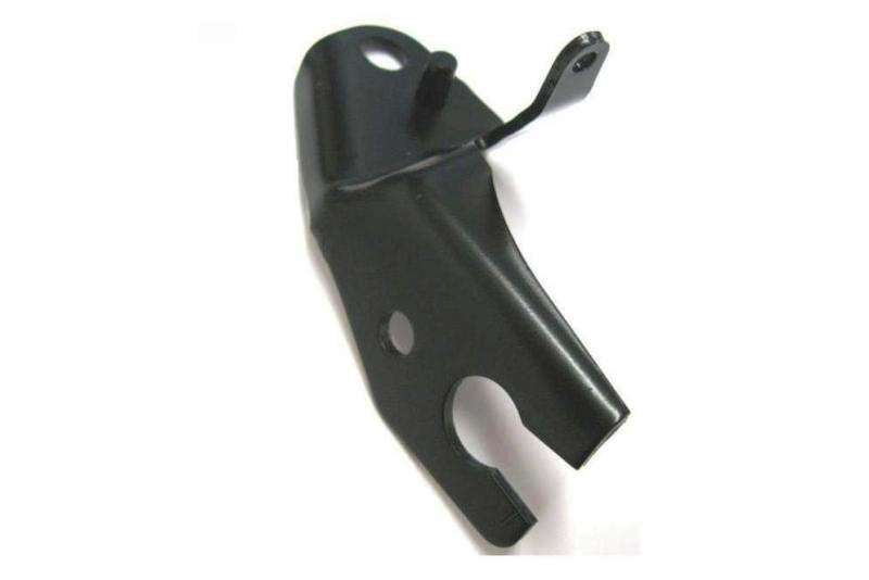 Here’s what the engine side looks like all back together:  I’ve decided to go ahead and order the 71-72 pedal pads with the stainless trim. As soon as they show up and get installed I’ll post some update photos. The Chevelle pad will get added to the parts collection.
__________________
My Build Thread: http://67-72chevytrucks.com/vboard/s...d.php?t=444502 Last edited by markeb01; 03-30-2012 at 07:49 PM. |
|
|

|
|
|
#24 |
|
Senior Enthusiast
Join Date: Feb 2007
Location: Spokane Valley, WA
Posts: 8,356
|
Re: Markeb01 Build Thread
Here are a couple of final photos. This one shows the mounting bolts for the gas pedal support, the cable attachment, and the block off plate for the old linkage pivot:
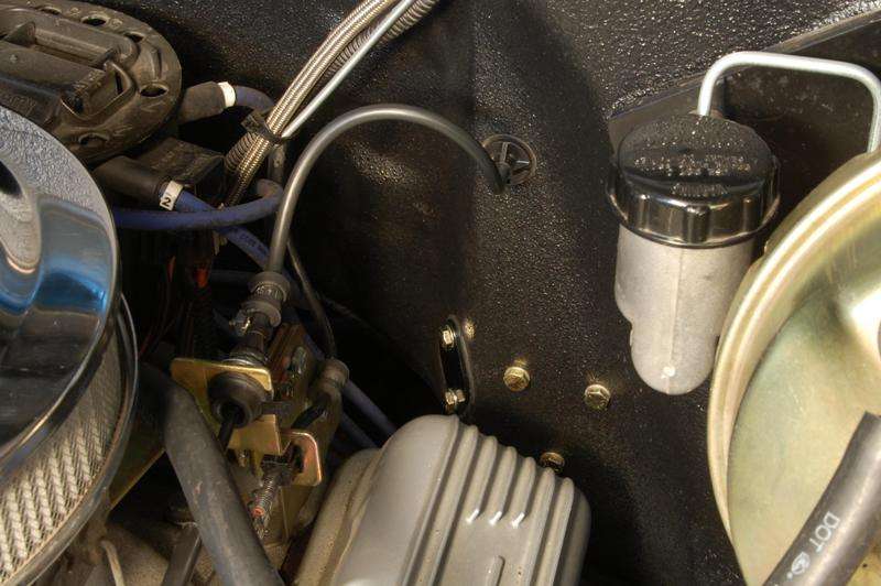 And this is the best shot I can get of the engine brackets. The new bracket moved the anchor for the throttle return springs back almost an inch and a half stretching them too tight. So I added a high tech adjustable return spring connector (a piece of dog choke chain). Once I dial in the correct length I’ll have my kid whip up something a little fancier looking. Obviously I need to wash my engine again.  Just took her out for the first drive with the new cable setup. What an unbelievable difference. I would have made the change years ago had I known how much of an improvement it was going to make. It is smooth as glass and extremely precise. The final minor adjustment was increasing throttle spring tension by one notch. The cruise control worked perfectly requiring no adjustment at all. Having been a mechanical linkage guy for the last 45 years I’m surprised how delighted I am with the results of this conversion. I’ll be recommending cable gas pedals from now on.
__________________
My Build Thread: http://67-72chevytrucks.com/vboard/s...d.php?t=444502 Last edited by markeb01; 04-01-2012 at 01:46 PM. |
|
|

|
|
|
#25 |
|
Registered User
Join Date: Nov 2009
Location: Galt, Calif
Posts: 2,437
|
Re: Markeb01 Build Thread
Quote:
__________________
`64 C10 vortec 350/350/373 posi `69 RS/SS 350/350/308 `37 Ford 406/350/324 traclock `68 Dart 370/904/323 suregrip |
|
|

|
 |
| Bookmarks |
|
|