
|
Register or Log In To remove these advertisements. |
|
|
|
|||||||
 |
|
|
Thread Tools | Display Modes |
 07-31-2015, 03:34 PM
|
#1 |
|
Registered User
Join Date: Jul 2015
Location: Inverness, Florida, USA
Posts: 62
|
Temperature Sensor Questions
Okay, my temperature gauge on my 1986 C10 hasn't worked since I purchased it. I tried all of the basics, such as grounding out the cable, and I have confirmed that the gauge works, and the wiring is okay, so this leads me to the temperature sensor itself.
I'm trying to test the sensor to see if it works, but I need to know: If I have the sensor out of the block, and I place it in boiling water with the wire connected ( but not submerged ), should the gauge move, or does the sensor have to be grounded as well as connected to the gauge to work? And if so, what part of the sensor do I have to ground? Thanks!
__________________
1987 Chevrolet Suburban R10 - 6.2L Detroit Diesel - 147k Miles
|

|

|
|
07-31-2015, 03:58 PM
|
#2 |
|
Registered User
Join Date: Aug 2012
Location: Oklahoma City, OK
Posts: 2,538
|
Re: Temperature Sensor Questions
Yes, has to be grounded to the truck.
Any part other then the connection terminal for the gauge wire. A couple of tight wraps of stranded bare copper wire around the freshly cleaned threads will usually do the trick. Just run a clip lead or similar to a good ground on the truck. |
|
|
|
|
07-31-2015, 04:28 PM
|
#3 | |
|
Registered User
Join Date: Jul 2015
Location: Inverness, Florida, USA
Posts: 62
|
Re: Temperature Sensor Questions
Quote:
__________________
1987 Chevrolet Suburban R10 - 6.2L Detroit Diesel - 147k Miles
|
|
|
|
|
|
08-01-2015, 03:15 AM
|
#4 |
|
Registered User
Join Date: Apr 2014
Location: Bloomington Indiana
Posts: 1,041
|
Re: Temperature Sensor Questions
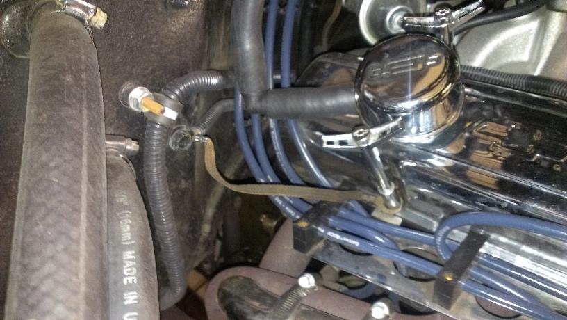
Do you have the ground wire from the engine to the cab? If this isn't there, the cab and the engine don't agree on what 0 volts is. You can see the copper braid in this pic. Doesn't have to be copper braid, can be any wire size 14 AWG or bigger.
__________________
Rich Weyand 1978 K10 RCSB DD. |
|
|
|
|
08-01-2015, 07:34 AM
|
#5 |
|
Registered User
Join Date: May 2007
Location: New Hampshire
Posts: 349
|
Re: Temperature Sensor Questions
You aren't using teflon tape on the threads are you?
Normally I would agree with Rich - that it might be a lack of a bonding strap from the RH cylinder head to the firewall/cab body - but that would effect all the gauges and you didn't mention any other problems. When you successfully tested it with an external jumper, where did you attach the free end of the jumper (the one not wrapped around the sender)? Did you ground it near the place on the head where the sender is normally mounted? If so, and it worked, this is a real "head scratcher". |
|
|
|
|
08-01-2015, 10:27 AM
|
#6 | ||
|
Registered User
Join Date: Jul 2015
Location: Inverness, Florida, USA
Posts: 62
|
Re: Temperature Sensor Questions
Quote:
 Quote:
__________________
1987 Chevrolet Suburban R10 - 6.2L Detroit Diesel - 147k Miles
|
||
|
|
|
|
08-01-2015, 05:59 PM
|
#7 |
|
Registered User
Join Date: Apr 2014
Location: Bloomington Indiana
Posts: 1,041
|
Re: Temperature Sensor Questions
Did you test it using the stock sensor wiring back to the gauge?
__________________
Rich Weyand 1978 K10 RCSB DD. |
|
|
|
|
08-01-2015, 07:49 PM
|
#8 |
|
Registered User
Join Date: May 2007
Location: New Hampshire
Posts: 349
|
Re: Temperature Sensor Questions
Wow - that's strange.
1. You take an artificially heated, uninstalled sender (that is connected normally to the factory wiring), you ground the body to the engine with a jumper and the dash indicator responds correctly - it moves away from the lowest reading and settles out somewhere around mid-range. 2. You disassemble the test rig, screw the sender into the cylinder head, reconnect the factory wiring to the terminal and start the engine. But now - even with the engine up to operating temperature - the gauge does not react at all. It stays at the low end of the indicated range. I'm going to have to go with an intermittent physical/mechanical problem in the gauge's sensing leg. IOW: somewhere along it's length, the stranded copper inside the insulation of the dark green wire is broken and only occasionally does the break close up and allow continuity. The sender end of that sensing leg (the dark green lead) lives in miserable conditions. The heat shields under the spark plugs are probably long since gone, so it is subjected to the extreme heat from the exhaust manifold. It is stretched pretty tight from where it exits the loom, runs along the valve cover and drops down to the sender. Also, and I don't know about your engine, it is normally coated with oily grime. Finally, and probably most importantly, it is 30 years old. I would inspect the wire carefully, starting at the sender connection and working back to the point where it goes down into the loom behind the distributor. I know most people hate to modify the factory wiring but in this case it might be worth it to splice in a new run - at least from the sender back to the loom. |
|
|
|
|
08-01-2015, 08:58 PM
|
#9 | ||
|
Registered User
Join Date: Jul 2015
Location: Inverness, Florida, USA
Posts: 62
|
Re: Temperature Sensor Questions
Quote:
Quote:
When the sender is out of the block, and I ground it by tying a wire around the threads and touching the compressor, it works. But when screwed back into the block, it doesn't work. But the block is grounded on the firewall. And if the compressor ( which is attached to the block ) works as a ground, shouldn't the block itself?
__________________
1987 Chevrolet Suburban R10 - 6.2L Detroit Diesel - 147k Miles
|
||
|
|
|
|
08-01-2015, 09:02 PM
|
#10 |
|
Registered User
Join Date: Apr 2014
Location: Bloomington Indiana
Posts: 1,041
|
Re: Temperature Sensor Questions
I think chengny may be on to something. Wire broken inside the insulation. I had that on my blower motor wire, from the resistor block to the motor. Every time I took it off and turned the connector to test it, it was fine, when I turned the connector back to the firewall and plugged it in, it didn't work.
__________________
Rich Weyand 1978 K10 RCSB DD. |
|
|
|
|
08-02-2015, 08:09 AM
|
#11 |
|
Registered User
Join Date: Aug 2012
Location: Oklahoma City, OK
Posts: 2,538
|
Re: Temperature Sensor Questions
One thing you might double check is the possibility that the gauge and sender ARE working correctly and the problem is a stuck open or missing thermostat.
Might use a battery terminal brush on the head sender port threads to clean the years of gunk and rust off. |
|
|
|
|
08-02-2015, 02:29 PM
|
#12 |
|
Registered User
Join Date: Jul 2015
Location: Inverness, Florida, USA
Posts: 62
|
Re: Temperature Sensor Questions
Thank you for all of the help guys, I got the temp. gauge working. I'm not sure what exactly the problem was, but I did the following, and it works.
- Ran new wire. - Added an extra ground to the block. - Cleaned the sender, connector, and threads on the block.  Now if only I could get my Voltmeter, Oil Pressure, and Fuel gauges working. 
__________________
1987 Chevrolet Suburban R10 - 6.2L Detroit Diesel - 147k Miles
|
|
|
|
|
08-03-2015, 12:32 AM
|
#13 |
|
Registered User
Join Date: May 2007
Location: New Hampshire
Posts: 349
|
Re: Temperature Sensor Questions
Use basically the same diagnostic procedure for the oil pressure indicator as you used for the coolant temperature indicator.
I don't mean to be a wiseguy but, you have checked that the 20 amp GAUGE/IDLE fuse right? That pink/black 39 circuit supplies all the gauges. Course you wouldn't have been able to get the coolant temp indicator to work if that fuse was blown - unless you ran a new hot wire. If you plan on really diving into your gauge issue, you might want to read the following. I wrote it as gas gauge specific, but the fundamentals apply to all the indicators (except the voltmeter): Just as a general discussion on the gauge/sender/chassis relationship - and to make sure I have the theory of operation straight in my mind; The components mentioned above - when connected by the pink and blue wires - form the "sensing leg" of the gas gauge located in the instrument panel. 12 volts is supplied to the positive terminal of the sender (via the pink wire). It's source is the negative side of the gauge's measuring coil. The less resistance in this total combined circuit, the greater the electron flow through the coil wires - and consequently the stronger the force is that it (the measuring coil) can exert on the gauge's magnet. The magnet is attached to the lower end of the indicating needle. In addition to the sensing leg, there is another - opposing - circuit called the "control leg". It is identical to the sensing leg in every way except that the negative side of it's coil is lead straight to ground (rather than through a variable resistance and then to ground like the sensing leg). Also, it's coil is located on the opposite side of the magnet from the measuring coil's. So what you have is; two coils located on either side of an indicating needle - AKA the "ray". The ray is pivoted somewhere in the middle and has an integral magnet mounted at the bottom. These coils create their own magnetic fields - the strength of which is a function of the electron flow (i.e. current) passing through them. When these circuits are energized - by turning the ignition switch to the RUN position - the opposing magnetic fields begin to "fight it out". Each coil tries to pull the magnet - mounted on the needle - towards itself. Due to the fact that it's negative leg is run straight to ground - resulting in nearly zero resistance, the current flow through the control coil is essentially constant (as is it's magnetic force). On the other hand, due to the variable resistance generated by the sender (as a result of changes in the fuel tank level), the current flow/magnetic strength of the measuring coil can be higher or lower than that of the control coil. The location of the two coils - to the magnet - is such that: 1. The control leg is always trying to peg the indicating ray to the FULL end. 2. The sensing leg is always trying to peg the ray to the EMPTY end. So as extreme examples: 1. If the pink wire to the sender is broken/disconnected the control leg exerts the greater force and pegs the needle Full. 2. If the pink wire is allowed to contact ground (before passing through the sender), the sensing leg has a greater force and the ray pegs low. As GM explains it (better and way more succinctly than I can): VARIABLE VOLTAGE TYPE The variable voltage type dash gauge consists of two magnetic coils to which battery voltage is applied. The coils act on the gauge pointer and pull in opposite directions. One coil is grounded directly to the chassis, while the other coil is grounded through a variable resistor within the sending unit. Resistance through the sending unit determines current flow through its coil, and therefore pointer position. When resistance is high in the sending unit, less current is allowed to flow through its coil, causing the gauge pointer to move toward the directly grounded coil. When resistance in the sending unit decreases, more current is allowed to pass through its coil, increasing the magnetic field. The gauge pointer is then attracted toward the coil which is grounded through the sending unit. |
|
|
|
|
| Bookmarks |
|
|


 Linear Mode

