 |
Register or Log In To remove these advertisements. |
|
|
|
|||||||
 |
|
|
Thread Tools | Display Modes |
|
|
#1 |
|
Registered User
 Join Date: Feb 2003
Location: Marshfield, MO
Posts: 355
|
Testing a fuel sending unit
When testing a fuel sending unit (90 ohm), should it read from 0 to 90? Or a range of 90? I tested mine tonight and the ohm reading was 20 to 110. Is that ok? Or am in the market for new sending unit?
Posted via Mobile Device Posted via Mobile Device |
|
|

|
|
|
#2 |
|
Registered User
Join Date: Nov 2009
Location: Sherman, ME
Posts: 2,366
|
Re: Testing a fuel sending unit
It should read 0 to 90.
Are you connecting your ohmmeter directly to the sending unit? Or are you doing your test through some of the truck's wiring? If you're measuring through the wiring, a bad wire or connection might possibly be the source of that extra 20 ohms. |
|
|

|
|
|
#3 |
|
Registered User
Join Date: May 2007
Location: New Hampshire
Posts: 349
|
Re: Testing a fuel sending unit
Fresh batteries in your VOM?
They are usually "out of sight out of mind" but for whatever reason, when they get weak resistance (and voltage) readings rise |
|
|

|
|
|
#4 | ||
|
Registered User
 Join Date: Feb 2003
Location: Marshfield, MO
Posts: 355
|
Re: Testing a fuel sending unit
Quote:
Quote:
Posted via Mobile Device Posted via Mobile Device |
||
|
|

|
|
|
#5 | |
|
Registered User
 Join Date: Feb 2003
Location: Marshfield, MO
Posts: 355
|
Re: Testing a fuel sending unit
Quote:
Posted via Mobile Device |
|
|
|

|
|
|
#6 |
|
Registered User
Join Date: May 2007
Location: New Hampshire
Posts: 349
|
Re: Testing a fuel sending unit
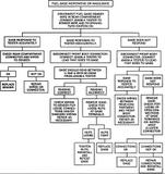
Here is the GM diagnostic flow chart for a faulty fuel gauge:
 It calls for a special tool but you can read between the lines. Simple wiring diagram:  And general info - note the bold type: Description and Operation Gauge failures are often caused by defective wiring or grounds. The first step in locating trouble should be a thorough inspection of all wiring, terminals and printed circuits. If wiring is secured by clamps, check to see whether the insulation has been severed, thereby grounding the wire. In the case of a fuel gauge installation, rust may cause failure by corrosion at the ground connection of the tank unit. VARIABLE VOLTAGE TYPE The variable voltage type dash gauge consists of two magnetic coils to which battery voltage is applied. The coils act on the gauge pointer and pull in opposite directions. One coil is grounded directly to the chassis, while the other coil is grounded through a variable resistor within the sending unit. Resistance through the sending unit determines current flow through its coil, and therefore pointer position. When resistance is high in the sending unit, less current is allowed to flow through its coil, causing the gauge pointer to move toward the directly grounded coil. When resistance in the sending unit decreases, more current is allowed to pass through its coil, increasing the magnetic field. The gauge pointer is then attracted toward the coil which is grounded through the sending unit. A special tester is required to diagnose this type gauge. Follow instructions included with the tester. Last edited by chengny; 12-09-2012 at 07:44 PM. |
|
|

|
|
|
#7 |
|
Registered User
 Join Date: Feb 2003
Location: Marshfield, MO
Posts: 355
|
Re: Testing a fuel sending unit
Chengny- thanks for the troubleshooting info. I saved them
 Posted via Mobile Device |
|
|

|
 |
| Bookmarks |
|
|