The 1947 - Present Chevrolet & GMC Truck Message Board Network


Register or Log In To remove these advertisements.

Go Back   The 1947 - Present Chevrolet & GMC Truck Message Board Network > 47 - Current classic GM Trucks > The 1973 - 1987 Chevrolet & GMC Squarebody Pickups Message Board

Web 67-72chevytrucks.com


Reply
 
Thread Tools Display Modes
Old 03-25-2013, 10:12 PM   #951
BigrobDog
Registered User
 
Join Date: Feb 2013
Location: Mandan
Posts: 80
Re: Tbi swap build thread

Quote:
Originally Posted by cjracing15 View Post
This thread is turning out to be what I wanted, A bunch of info on this swap that you don't have to hunt and hunt for on the net at a ton of different sites.

Keep the info comming. Please share what you have done and if you have a question, please ask it.

I am going to have some more progress pics on my swap tomarrow so stay tune.
so if my vss wires from tranny plugs right in to harness it should be hooked up ,and no need to wire any thing.or ground them,
BigrobDog is offline   Reply With Quote
Old 03-25-2013, 10:32 PM   #952
BigrobDog
Registered User
 
Join Date: Feb 2013
Location: Mandan
Posts: 80
Re: Tbi swap build thread

Quote:
Originally Posted by cjracing15 View Post
Well I got a little futher along today. I finnally got all the under hood wires and under the dash wires run.
I droped the stock tank and, it is a good thing I did it was just about to rust through. I changed out the old stock pump in my EFI tank with a new pump and, ran my lines from the tank to the switching valve. Also ran the lines along the frame up to the throtle body.

I pluged in my cluster and wired my Check engine light and turned on the ignition and presto all my lights worked.

All I like now is installing my EFI tank, wire the pump, change the orings for the throttle body gas lines, put my pullys back on the engine. Then fire that mother up!

Pics tomarrow.(I left the camera at dads shop)
do you know what wires go to check engine light,and to the aldl plug. by there color.
BigrobDog is offline   Reply With Quote
Old 03-26-2013, 02:30 AM   #953
rfmaster
Registered User
 
rfmaster's Avatar
 
Join Date: Oct 2003
Location: OC CA
Posts: 1,374
Re: Tbi swap build thread

@BigrobDog

OK - thanks for posting photographs - these help quiet a bit.

In Photo # 1
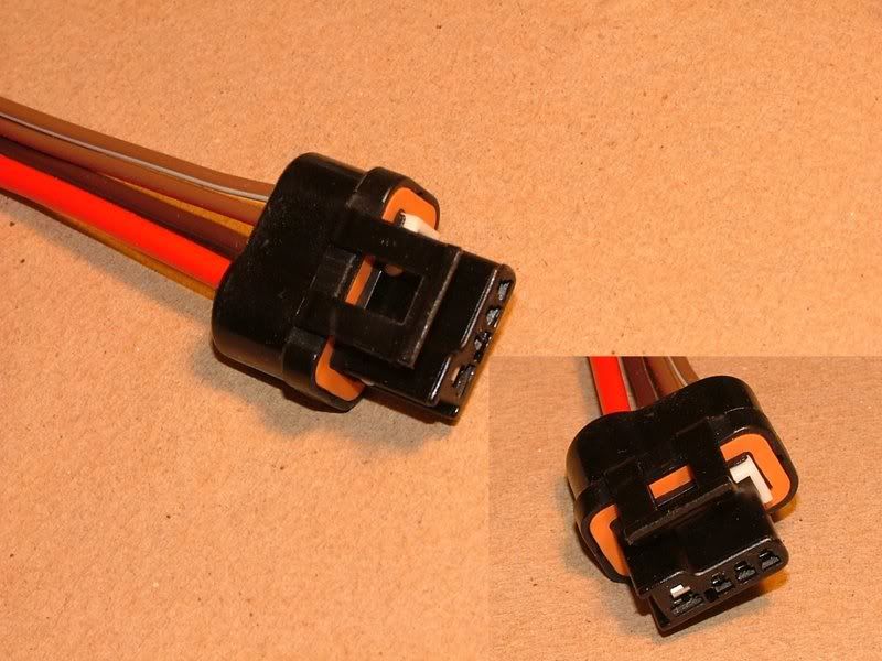
Your 1990 burban donor came equipped with CS-130 Alternator. This alternator has internal regulator. OE external '72 regulator that you have in Photo #2 will not be used. To adapt CS 130 to the '72 wiring is actually straight forward, but it will require a bit of DIY soldering. Are you up for it????

CS130 alternator is rated for 105AMPS maximum output and will deliver around 30 to 35Amps at idle. Which is plenty.

Look at the back of alternator. There, you should see BAT terminal and big fat red wire should be running between alternator BAT terminal and terminal block that is part of EFI harness - mounted on the passenger side firewall. I thinks there is one, but it is taped-up and not clearly visible. That wire should have been a part of '90 burban harness. From the firewall mounted terminal block there also should be a big red wire running to starter main terminal - its also should be a very thick red wire - 8AWG. Please take a close look and capture a photo of it in case if it is not connected. A fuel pump relay should be in close proximity to that firewall mounted terminal block.

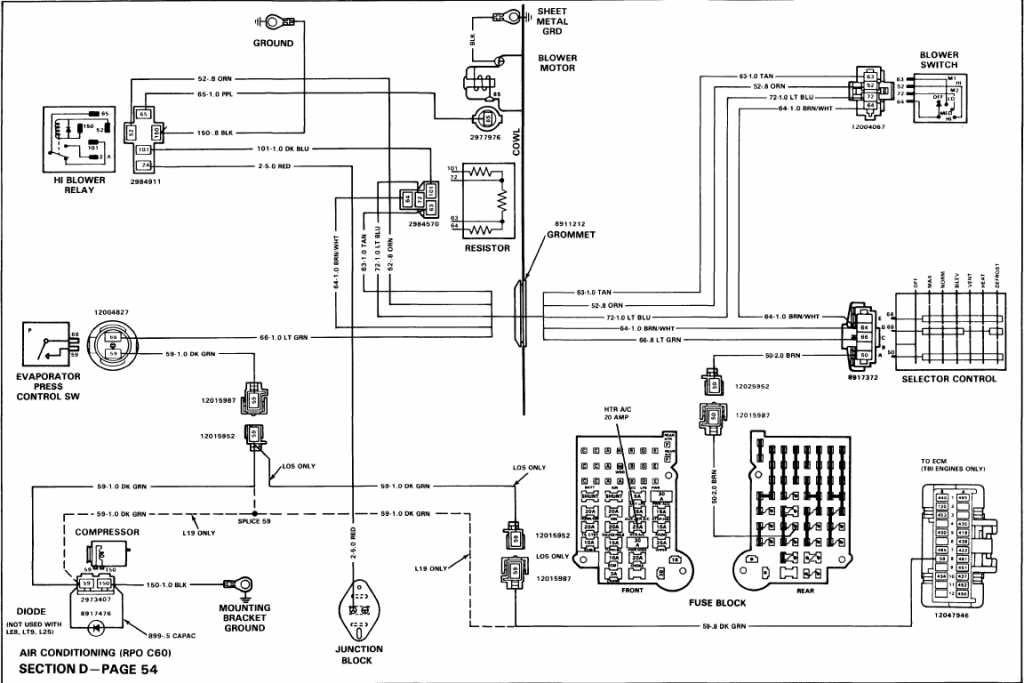
Back to CS-130 alternator. There is a multi pin plug with several wires protruding from it.. Most often it is just a brown 16 AWG wire tied to 'L' terminal. This is a alternator light bulb wire. You can NOT connect this wire directly to the instrument alternator light. This connection can only be made if there is a series 150 to 300 OHM 1Watt resistor ( between alternator plug and instrument cluster alternator light). This is done by disconnecting external regulator plug from OE external regulator module and connecting brown wire from CS-130 'L' circuit with a series resistor to terminal 4 of the OE regulator plug - also brown wire. At least GM was consistent with their wire color schemes over decades! . Schematic below does not show this resistor, but it must be there.


Sometime, there is a larger gauge red wire tied to S terminal - this is a voltage sense line. This wire should be tied to a BAT terminal block on the firewall.

Photo #3
This is a tough one - this portion of the harness was connected to 90 burban main feed through block. The wires protruding maybe useless - anti lock computer, windshield wiper motor, temperature sensor, etc. It is best to remove split loom and peel off electrical tape and determine where these wires went.

VSS - this is a long discussion in itself. Do you have 700R4 from donor or you still have THM-350/400???

P/N switch - some DIY is involved but can be easily implemented. Search this thread for schematic.

//RF
__________________
"The Beast"

1975 Chevrolet C20 longbed
350/700R4! with 3inch body lift
Dual Flowmasters Super 40's!
TBI retrofit completed (2007-07-29)
New 383CID (+030) 08-304-8 9.5:1CR x36,005 (2012-12-17)
rfmaster is offline   Reply With Quote
Old 03-26-2013, 06:50 AM   #954
BigrobDog
Registered User
 
Join Date: Feb 2013
Location: Mandan
Posts: 80
Re: Tbi swap build thread

no i have the 700r4 . its all suburban put 72 over the top
Attached Images
   
BigrobDog is offline   Reply With Quote
Old 03-26-2013, 10:58 AM   #955
jasons
not enough hours in the day
 
jasons's Avatar
 
Join Date: Jan 2009
Location: Axtell, NE
Posts: 550
Re: Tbi swap build thread

Quote:
Originally Posted by rfmaster View Post
@BigrobDog


Back to CS-130 alternator. There is a multi pin plug with several wires protruding from it.. Most often it is just a brown 16 AWG wire tied to 'L' terminal. This is a alternator light bulb wire. You can NOT connect this wire directly to the instrument alternator light. This connection can only be made if there is a series 150 to 300 OHM 1Watt resistor ( between alternator plug and instrument cluster alternator light). This is done by disconnecting external regulator plug from OE external regulator module and connecting brown wire from CS-130 'L' circuit with a series resistor to terminal 4 of the OE regulator plug - also brown wire. At least GM was consistent with their wire color schemes over decades! . Schematic below does not show this resistor, but it must be there.


//RF
I wired my alternator like this diagram. This is the first I've heard of needing a resistor in the 'L' circuit. You mention the instrument alternator light, is the resistor just required with the idiot light panel or is it also needed with the guages?
__________________
65 K-10 Short Step
68 C-50
70 K-5
85 K-10
& piles of spare parts
jasons is offline   Reply With Quote
Old 03-26-2013, 11:08 AM   #956
rfmaster
Registered User
 
rfmaster's Avatar
 
Join Date: Oct 2003
Location: OC CA
Posts: 1,374
Re: Tbi swap build thread

Oh wow - it is nice to have a power lift -> CAT!

With VSS you have a small problem. The 90 burban uses electronic speedometer, while '72 truck is a classic mechanical unit.
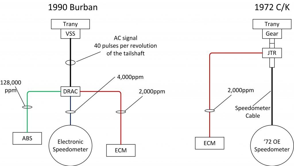


To solve this you'll need to find a mechanical speedometer gear cable unit from an earlier 700R4 and add an inline 2000 ppm VSS unit from JTR.com. For example AC-Delco 25512339. But first you need to figure out which speedometer gears to use before ordering.
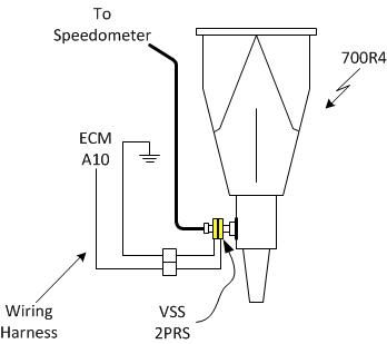


Also complicating conversion is that you have a 4x4 burban and VSS may have been installed in a transfer case (I simply do not know).

//RF
__________________
"The Beast"

1975 Chevrolet C20 longbed
350/700R4! with 3inch body lift
Dual Flowmasters Super 40's!
TBI retrofit completed (2007-07-29)
New 383CID (+030) 08-304-8 9.5:1CR x36,005 (2012-12-17)
rfmaster is offline   Reply With Quote
Old 03-26-2013, 11:17 AM   #957
rfmaster
Registered User
 
rfmaster's Avatar
 
Join Date: Oct 2003
Location: OC CA
Posts: 1,374
Re: Tbi swap build thread

Quote:
Originally Posted by jasons View Post
I wired my alternator like this diagram. This is the first I've heard of needing a resistor in the 'L' circuit. You mention the instrument alternator light, is the resistor just required with the idiot light panel or is it also needed with the guages?
Please see this thread - CS-130 conversion from 10 DN
http://67-72chevytrucks.com/vboard/s...d.php?t=436742
__________________
"The Beast"

1975 Chevrolet C20 longbed
350/700R4! with 3inch body lift
Dual Flowmasters Super 40's!
TBI retrofit completed (2007-07-29)
New 383CID (+030) 08-304-8 9.5:1CR x36,005 (2012-12-17)
rfmaster is offline   Reply With Quote
Old 03-26-2013, 11:40 AM   #958
jasons
not enough hours in the day
 
jasons's Avatar
 
Join Date: Jan 2009
Location: Axtell, NE
Posts: 550
Re: Tbi swap build thread

Thanks again RF. I hadn't seen that thread. Glad to know this before firing it up and wondering why it didn't charge properly.
__________________
65 K-10 Short Step
68 C-50
70 K-5
85 K-10
& piles of spare parts
jasons is offline   Reply With Quote
Old 03-26-2013, 09:21 PM   #959
BigrobDog
Registered User
 
Join Date: Feb 2013
Location: Mandan
Posts: 80
Re: Tbi swap build thread

Quote:
Originally Posted by rfmaster View Post
Oh wow - it is nice to have a power lift -> CAT!

With VSS you have a small problem. The 90 burban uses electronic speedometer, while '72 truck is a classic mechanical unit.


To solve this you'll need to find a mechanical speedometer gear cable unit from an earlier 700R4 and add an inline 2000 ppm VSS unit from JTR.com. For example AC-Delco 25512339. But first you need to figure out which speedometer gears to use before ordering.


Also complicating conversion is that you have a 4x4 burban and VSS may have been installed in a transfer case (I simply do not know).

//RF
i think it is on the back of the transfer case on the out put of yoke.but i dont think u can add a mechanical cable .
BigrobDog is offline   Reply With Quote
Old 03-26-2013, 09:53 PM   #960
BigrobDog
Registered User
 
Join Date: Feb 2013
Location: Mandan
Posts: 80
Re: Tbi swap build thread

Quote:
Originally Posted by rfmaster View Post
@BigrobDog

OK - thanks for posting photographs - these help quiet a bit.

In Photo # 1
Your 1990 burban donor came equipped with CS-130 Alternator. This alternator has internal regulator. OE external '72 regulator that you have in Photo #2 will not be used. To adapt CS 130 to the '72 wiring is actually straight forward, but it will require a bit of DIY soldering. Are you up for it????

CS130 alternator is rated for 105AMPS maximum output and will deliver around 30 to 35Amps at idle. Which is plenty.

Look at the back of alternator. There, you should see BAT terminal and big fat red wire should be running between alternator BAT terminal and terminal block that is part of EFI harness - mounted on the passenger side firewall. I thinks there is one, but it is taped-up and not clearly visible. That wire should have been a part of '90 burban harness. From the firewall mounted terminal block there also should be a big red wire running to starter main terminal - its also should be a very thick red wire - 8AWG. Please take a close look and capture a photo of it in case if it is not connected. A fuel pump relay should be in close proximity to that firewall mounted terminal block.

Back to CS-130 alternator. There is a multi pin plug with several wires protruding from it.. Most often it is just a brown 16 AWG wire tied to 'L' terminal. This is a alternator light bulb wire. You can NOT connect this wire directly to the instrument alternator light. This connection can only be made if there is a series 150 to 300 OHM 1Watt resistor ( between alternator plug and instrument cluster alternator light). This is done by disconnecting external regulator plug from OE external regulator module and connecting brown wire from CS-130 'L' circuit with a series resistor to terminal 4 of the OE regulator plug - also brown wire. At least GM was consistent with their wire color schemes over decades! . Schematic below does not show this resistor, but it must be there.


Sometime, there is a larger gauge red wire tied to S terminal - this is a voltage sense line. This wire should be tied to a BAT terminal block on the firewall.

Photo #3
This is a tough one - this portion of the harness was connected to 90 burban main feed through block. The wires protruding maybe useless - anti lock computer, windshield wiper motor, temperature sensor, etc. It is best to remove split loom and peel off electrical tape and determine where these wires went.

VSS - this is a long discussion in itself. Do you have 700R4 from donor or you still have THM-350/400???

P/N switch - some DIY is involved but can be easily implemented. Search this thread for schematic.

//RF
your showing a 4 prong plug i only have 2 prong plug brown / and orange.. so brown to 4 plug and and orange to back of + alternator. is this right , nothing at all will be hook to external 72 regulator.is power wier to dash were the light goes , or is that voltage out put.
BigrobDog is offline   Reply With Quote
Old 03-26-2013, 09:54 PM   #961
BigrobDog
Registered User
 
Join Date: Feb 2013
Location: Mandan
Posts: 80
Re: Tbi swap build thread

Quote:
Originally Posted by rfmaster View Post
@BigrobDog

OK - thanks for posting photographs - these help quiet a bit.

In Photo # 1
Your 1990 burban donor came equipped with CS-130 Alternator. This alternator has internal regulator. OE external '72 regulator that you have in Photo #2 will not be used. To adapt CS 130 to the '72 wiring is actually straight forward, but it will require a bit of DIY soldering. Are you up for it????

CS130 alternator is rated for 105AMPS maximum output and will deliver around 30 to 35Amps at idle. Which is plenty.

Look at the back of alternator. There, you should see BAT terminal and big fat red wire should be running between alternator BAT terminal and terminal block that is part of EFI harness - mounted on the passenger side firewall. I thinks there is one, but it is taped-up and not clearly visible. That wire should have been a part of '90 burban harness. From the firewall mounted terminal block there also should be a big red wire running to starter main terminal - its also should be a very thick red wire - 8AWG. Please take a close look and capture a photo of it in case if it is not connected. A fuel pump relay should be in close proximity to that firewall mounted terminal block.

Back to CS-130 alternator. There is a multi pin plug with several wires protruding from it.. Most often it is just a brown 16 AWG wire tied to 'L' terminal. This is a alternator light bulb wire. You can NOT connect this wire directly to the instrument alternator light. This connection can only be made if there is a series 150 to 300 OHM 1Watt resistor ( between alternator plug and instrument cluster alternator light). This is done by disconnecting external regulator plug from OE external regulator module and connecting brown wire from CS-130 'L' circuit with a series resistor to terminal 4 of the OE regulator plug - also brown wire. At least GM was consistent with their wire color schemes over decades! . Schematic below does not show this resistor, but it must be there.


Sometime, there is a larger gauge red wire tied to S terminal - this is a voltage sense line. This wire should be tied to a BAT terminal block on the firewall.

Photo #3
This is a tough one - this portion of the harness was connected to 90 burban main feed through block. The wires protruding maybe useless - anti lock computer, windshield wiper motor, temperature sensor, etc. It is best to remove split loom and peel off electrical tape and determine where these wires went.

VSS - this is a long discussion in itself. Do you have 700R4 from donor or you still have THM-350/400???

P/N switch - some DIY is involved but can be easily implemented. Search this thread for schematic.

//RF
your showing a 4 prong plug i only have 2 prong plug brown / and orange.. so brown to 4 plug and and orange to back of + alternator. is this right , nothing at all will be hook to external 72 regulator.is power wire to dash were the light goes , or is that voltage out put.
BigrobDog is offline   Reply With Quote
Old 03-26-2013, 11:12 PM   #962
rfmaster
Registered User
 
rfmaster's Avatar
 
Join Date: Oct 2003
Location: OC CA
Posts: 1,374
Re: Tbi swap build thread

Quote:
Originally Posted by BigrobDog View Post
your showing a 4 prong plug i only have 2 prong plug brown / and orange.. so brown to 4 plug and and orange to back of + alternator. is this right , nothing at all will be hook to external 72 regulator.is power wire to dash were the light goes , or is that voltage out put.
@BigRobDog

Take a look at your CS-130 plug.


In most case it will have only two wires populated - Large red and smaller gauge brown. The red goes to terminal labeled 'S' and brown goes to 'L'. Terminal letters are hard to see but they are part of plug body!!!

Disconnect plug from OE '72 external voltage regulator shown in the photo below...


extend wire from CS-130 plug 'L' terminal to reach terminal #4 of the OE '72 external voltage regulator.

//RF
__________________
"The Beast"

1975 Chevrolet C20 longbed
350/700R4! with 3inch body lift
Dual Flowmasters Super 40's!
TBI retrofit completed (2007-07-29)
New 383CID (+030) 08-304-8 9.5:1CR x36,005 (2012-12-17)
rfmaster is offline   Reply With Quote
Old 03-29-2013, 08:21 PM   #963
rfmaster
Registered User
 
rfmaster's Avatar
 
Join Date: Oct 2003
Location: OC CA
Posts: 1,374
Re: Tbi swap build thread

CS-130 Alternator swap info

http://67-72chevytrucks.com/vboard/s...d.php?t=567472
__________________
"The Beast"

1975 Chevrolet C20 longbed
350/700R4! with 3inch body lift
Dual Flowmasters Super 40's!
TBI retrofit completed (2007-07-29)
New 383CID (+030) 08-304-8 9.5:1CR x36,005 (2012-12-17)
rfmaster is offline   Reply With Quote
Old 03-30-2013, 11:12 AM   #964
jasons
not enough hours in the day
 
jasons's Avatar
 
Join Date: Jan 2009
Location: Axtell, NE
Posts: 550
Re: Tbi swap build thread

I wired B8 for the AC signal into the dark green lead to the compressor. Now with the compressor pluged in there is continuity between B8 and B1 which is a 12v battery wire hooked to a junction block and also between B8 and B3 the black/red wire to the distributor plug. Is this normal?
It makes me think the AC would always be engaged.
The compressor that is on the engine now is locked up and will be replaced, could this be the cause?
__________________
65 K-10 Short Step
68 C-50
70 K-5
85 K-10
& piles of spare parts
jasons is offline   Reply With Quote
Old 03-30-2013, 03:03 PM   #965
rfmaster
Registered User
 
rfmaster's Avatar
 
Join Date: Oct 2003
Location: OC CA
Posts: 1,374
Re: Tbi swap build thread

Quote:
Originally Posted by jasons View Post
I wired B8 for the AC signal into the dark green lead to the compressor. Now with the compressor pluged in there is continuity between B8 and B1 which is a 12v battery wire hooked to a junction block and also between B8 and B3 the black/red wire to the distributor plug. Is this normal?
It makes me think the AC would always be engaged.
The compressor that is on the engine now is locked up and will be replaced, could this be the cause?
B8 is AC signal ON input signal to ECM. So unless AC -heater selector switch is set in AC operate position and evaporator pressure control switch is closed there should not be +12 V at B8.


It is an input signal to ECM indicating that compressor clutch has been engaged. Move AC control selector and see if this voltage goes away when move AC to heater position (no AC).

//RF
__________________
"The Beast"

1975 Chevrolet C20 longbed
350/700R4! with 3inch body lift
Dual Flowmasters Super 40's!
TBI retrofit completed (2007-07-29)
New 383CID (+030) 08-304-8 9.5:1CR x36,005 (2012-12-17)
rfmaster is offline   Reply With Quote
Old 03-31-2013, 10:21 AM   #966
BigrobDog
Registered User
 
Join Date: Feb 2013
Location: Mandan
Posts: 80
Re: Tbi swap build thread

Quote:
Originally Posted by rfmaster View Post
I hate to say but this is not entirely correct. 87 to 89 Full-size trucks used a programmable DRAC module that is incorporated into the instrument panel. Starting '89 all Chevy trucks with rear wheel anti-lock brakes used electronic speedometers. Vehicle speed is monitored by a sensor (AC VSS) mounted on the output shaft of the transmission, where a speedometer cable would normally be installed (exception being 4x4). The signal generated by that sensor (40 pulses per driveshaft revolution) goes to the DRAC (blue and yellow wires) which further divides and conditions the signal for the electronic speedometer, ECM, cruise control and anti-lock brakes. Because of numerous gear ratios and tires there are different DRAC modules. Back in those days switching to taller tires caused a lot of grief as anti lock computer would flake out (same went for cruise control).

In 4x4 applications the VSS is mounted in a transfer case. This VSS (supplies 40 pulse AC signal per shaft revolution) can not be used without DRAC module since DRAC ultimately supplies 2000 ppm signal to ECM.

There are several issues that should be considered before installing donor drive line into '65.

First 700R4 have been known to have weak 3-4 band as well as many other weaknesses identified elsewhere on this board. All of them can be easily corrected by a competent trany shop while you have drive line out. It does not cost too much as long as hard parts are not damaged. The choice is yours.

Second. To get a functioning speedometer in your 65 you'll have to perform a minor retrofit. 700R4 that you have was configured for 4x4 duty with special output shaft adapter to transfer case (NP208???) which does not provide for conventional mechanical speedometer mounting flange! The only other place to get mechanical speedometer drive is from transfer case and that will depend on a transfer case. You'll have to figure out which transfer case you have - search 4x4 forums for speedometer retrofit thereafter. In the end you may find that having mechanical speedometer in your 65 may not be possible.

Third. To get ECM working right you'll have to extract DRAC module from your instrument cluster - this module typically has a three letter coded label attached to it. You'll have to research cluster wiring for '89 to determine which wires from DRAC were used to power it up and to supply ECM with 2000ppm signal.

Fourth. From photo's it appears that you have lots cut wires in your harness. Make a list of color and wire gauge of these cut wires. This way we can figure out what was cut and how to fix it.

Fifth. Clean up - it is a lot easier to work on engine that does not have oil leaks! Sorry, to point out obvious stuff.

Post your questions and findings - this very interesting since this is a very first 4x4 TBI retrofit!

//RF
check out this site tells alot about the vss, http://www.tbichips.com/drac/
BigrobDog is offline   Reply With Quote
Old 03-31-2013, 12:20 PM   #967
BigrobDog
Registered User
 
Join Date: Feb 2013
Location: Mandan
Posts: 80
Re: Tbi swap build thread

Quote:
Originally Posted by rfmaster View Post
Well - not that simple. While it is true ECM needs IGN and BAT (+12volt), you also need to connect IGN +12 for injectors, P/N switch, brake switch, TC control for 350C or 700R4 trany and VSS to make the best out of ECM.

//RF
what wire are my brake switch on the tbi to ecm so i can tie in to thoes , or is the a post are page on that all ready
BigrobDog is offline   Reply With Quote
Old 03-31-2013, 01:31 PM   #968
BigrobDog
Registered User
 
Join Date: Feb 2013
Location: Mandan
Posts: 80
Re: Tbi swap build thread

Quote:
Originally Posted by BigrobDog View Post
i think it is on the back of the transfer case on the out put of yoke.but i dont think u can add a mechanical cable .
Oh wow - it is nice to have a power lift -> CAT! ,, I just read that , funny , ya im a diesel mechanic and have the shop to my self on the weekend. , but my question is , I have read all 39 pages and have learned alot about tbi , my truck halls ass down the road . one problem im having is when I smash the pedal it get no response, have to ease in to it . then it gets on it , is that because of the drac , i have the 4x4 . and when reading all the post sounds like on the 4x4 model that the drac is used to run the speedometer . and another question is my brake switch is not hooked up to my harness what wire is that on my tbi harness, i love this tread , thanks for all the help.
BigrobDog is offline   Reply With Quote
Old 03-31-2013, 04:03 PM   #969
rfmaster
Registered User
 
rfmaster's Avatar
 
Join Date: Oct 2003
Location: OC CA
Posts: 1,374
Re: Tbi swap build thread

Quote:
Originally Posted by BigrobDog View Post
what wire are my brake switch on the tbi to ecm so i can tie in to thoes , or is the a post are page on that all ready
You'll have to take a look at your brake light switch. If it only has one set of contacts which are used for operating brake lights (N.O.) you'll have to replace it with one that has two sets of contacts AC-Delco 25524845, SMP-SLS159 (plus other after market part numbers. The new switch has NO and NC set of contacts. NO is used with brake lights, and NC will be used with TCC + ECM.

The TCC wiring diagram will depend on internal harness installed inside 700R4. Depending on application GM had different transmission case harness. And this is why I am not going to even attempt to suggest how to wire up TCC at this time. There is a 'cat' in transmission forum clinebarger - he knows more about 700R4 than GM! Ask him a question about TCC converter harness inside your trany. You'll have to post transmission ID (aka build configuration) stamped on the oil pan flange, back passenger side.


//RF
__________________
"The Beast"

1975 Chevrolet C20 longbed
350/700R4! with 3inch body lift
Dual Flowmasters Super 40's!
TBI retrofit completed (2007-07-29)
New 383CID (+030) 08-304-8 9.5:1CR x36,005 (2012-12-17)
rfmaster is offline   Reply With Quote
Old 04-01-2013, 09:49 PM   #970
BigrobDog
Registered User
 
Join Date: Feb 2013
Location: Mandan
Posts: 80
Re: Tbi swap build thread

Rf or cj I got a question , need some help here 72 chevy truck on 1990 suburban fram with tbi .

Q1, fuse next to fuel pump relay, gray wire in and gray wire out fuse in the middle. ok one side is hot other side is ground while truck is off, is this because of the computer . are do u know why this is.

Q2, gray box , just up from the computer,3'' long 1 1/2 wide with purple wires going in to it. it opens on one end ,I opened it and it was a small circuit board.

Q3, I have my old seedometer and on the back of it is a circuit board attached to it is this my drac,and if so how do i wire this up.
BigrobDog is offline   Reply With Quote
Old 04-03-2013, 10:42 PM   #971
jasons
not enough hours in the day
 
jasons's Avatar
 
Join Date: Jan 2009
Location: Axtell, NE
Posts: 550
Re: Tbi swap build thread

I just tried it for the first time. It fired right up, but idles at 1,800 RPM

The timing is set at 0* the tan/black wire unplugged, but I was checking this at the fast rpm's.

I cleaned up the throttle body and put a rebuild kit in it while averything was apart. Other than not getting something right when putting it together I'm at a loss for what would cause this.

Any ideas where to look?
__________________
65 K-10 Short Step
68 C-50
70 K-5
85 K-10
& piles of spare parts
jasons is offline   Reply With Quote
Old 04-04-2013, 12:02 AM   #972
rfmaster
Registered User
 
rfmaster's Avatar
 
Join Date: Oct 2003
Location: OC CA
Posts: 1,374
Re: Tbi swap build thread

Quote:
Originally Posted by jasons View Post
I just tried it for the first time. It fired right up, but idles at 1,800 RPM

The timing is set at 0* the tan/black wire unplugged, but I was checking this at the fast rpm's.

I cleaned up the throttle body and put a rebuild kit in it while averything was apart. Other than not getting something right when putting it together I'm at a loss for what would cause this.

Any ideas where to look?
You must perform IAC reset. Search thread - procedure has been posted. Also make sure that IAC has been screwed into TB firmly with a paper gasket. Also check position of your throttle blades - they should be almost touching walls. Minimum idle screw should keep the blades from coming in contact with the walls. Do not touch it at his time until you go through IAC reset couple of times.

Setting base timing at 1800 RPM is ok for starters, but it is better to do this while engine is idling around 650 RPM.

As always check for gross vacuum leaks around intake - PCV, CCP, brake booster line, etc.
__________________
"The Beast"

1975 Chevrolet C20 longbed
350/700R4! with 3inch body lift
Dual Flowmasters Super 40's!
TBI retrofit completed (2007-07-29)
New 383CID (+030) 08-304-8 9.5:1CR x36,005 (2012-12-17)
rfmaster is offline   Reply With Quote
Old 04-04-2013, 07:20 PM   #973
jasons
not enough hours in the day
 
jasons's Avatar
 
Join Date: Jan 2009
Location: Axtell, NE
Posts: 550
Re: Tbi swap build thread

Quote:
Originally Posted by rfmaster View Post
You must perform IAC reset. Search thread - procedure has been posted. Also make sure that IAC has been screwed into TB firmly with a paper gasket. Also check position of your throttle blades - they should be almost touching walls. Minimum idle screw should keep the blades from coming in contact with the walls. Do not touch it at his time until you go through IAC reset couple of times.

Setting base timing at 1800 RPM is ok for starters, but it is better to do this while engine is idling around 650 RPM.

As always check for gross vacuum leaks around intake - PCV, CCP, brake booster line, etc.
I did the IAC reset as you outlined in another thread 4 times with no difference.
I went through the steps with the IAC removed from the throttle body just to see what happened. The motor ran, but the plunger did not move. I gave it a push and it went in easily, then pulled and it came completely out. I realize I need to get a new one. I ran the engine with the IAC installed after this both with the plunger extended all the way by the spring and again with the plunger completely removed thinking that one of these would bring the idle down. Neither way changed it.
How does the IAC work, I assume it closes to cut off excess air and opens just enough to get the right idle speed.

I also checked the throttle blades, they are up against the wall of the throttle body with mabey a very small gap. The idle screw still has the cap over it.

I don't detect any vacuum leaks.
__________________
65 K-10 Short Step
68 C-50
70 K-5
85 K-10
& piles of spare parts
jasons is offline   Reply With Quote
Old 04-04-2013, 08:05 PM   #974
rfmaster
Registered User
 
rfmaster's Avatar
 
Join Date: Oct 2003
Location: OC CA
Posts: 1,374
Re: Tbi swap build thread

OK - yes, you'll need to get IAC replaced.

When you go through the IAC reset the plunger should extend fully and close off air bypass passage. You should hear a clicking noise while ALDL pins A & B are tied together and IAC is plugged into the harness. SES light should be on as well. Your assumption about how IAC operates are correct.

Lets address IAC operation first before moving any further. I assume that EGR valve is installed, but vacuum hose is disconnected???

The other items to be aware of - make sure that all harness ground connections are tied to their respective grounds. There are two main ones - in front by the thermostat housing and one in the back of the passenger cylinder head. Loose grounds will drive ECM nuts!!!

//RF
__________________
"The Beast"

1975 Chevrolet C20 longbed
350/700R4! with 3inch body lift
Dual Flowmasters Super 40's!
TBI retrofit completed (2007-07-29)
New 383CID (+030) 08-304-8 9.5:1CR x36,005 (2012-12-17)
rfmaster is offline   Reply With Quote
Old 04-04-2013, 08:23 PM   #975
jasons
not enough hours in the day
 
jasons's Avatar
 
Join Date: Jan 2009
Location: Axtell, NE
Posts: 550
Re: Tbi swap build thread

Quote:
Originally Posted by rfmaster View Post
OK - yes, you'll need to get IAC replaced.

When you go through the IAC reset the plunger should extend fully and close off air bypass passage. You should hear a clicking noise while ALDL pins A & B are tied together and IAC is plugged into the harness. SES light should be on as well. Your assumption about how IAC operates are correct.

Lets address IAC operation first before moving any further. I assume that EGR valve is installed, but vacuum hose is disconnected???

The other items to be aware of - make sure that all harness ground connections are tied to their respective grounds. There are two main ones - in front by the thermostat housing and one in the back of the passenger cylinder head. Loose grounds will drive ECM nuts!!!

//RF
The IAC did click when A&B pins were jumpered, I'm just not sure the plunger extended completely, the new IAC valve will be here in a couple hours.

The EGR valve is installed and the vacuum hose is connected. Should it be disconnected for this?

I will double check grounds at the ecm plug.
__________________
65 K-10 Short Step
68 C-50
70 K-5
85 K-10
& piles of spare parts
jasons is offline   Reply With Quote
Reply

Bookmarks


Posting Rules
You may not post new threads
You may not post replies
You may not post attachments
You may not edit your posts

BB code is On
Smilies are On
[IMG] code is On
HTML code is Off

Forum Jump


All times are GMT -4. The time now is 08:24 PM.


Powered by vBulletin® Version 3.8.11
Copyright ©2000 - 2025, vBulletin Solutions Inc.
Copyright 1997-2022 67-72chevytrucks.com