 |
Register or Log In To remove these advertisements. |
|
|
|
|||||||
 |
|
|
Thread Tools | Display Modes |
|
|
#1 |
|
Registered User
Join Date: Sep 2012
Location: CT
Posts: 133
|
Water Temp and Oil Pressure wire identification.
Trying to finish piecing together the wiring on my truck and tuck everything nicely, I'm having issues identifying my sending unit wires. I'm using an 84' engine bay wiring harness with an 87' cab and internals.
As of now, after reading a few threads of diagrams, I have my light brown/dark tan wire (still has the factory boot on it) to my oil pressure sender and it is NOT reading at the gauge. The gauge is bottomed out in the clockwise position. I have to take an overdue trip to the parts store to pick up some spade connectors for my water temp sending unit, right now I'm assuming that the dark green wire is what I should be using. Correct? I would really appreciate some pictures. |
|
|

|
|
|
#2 |
|
Registered User
Join Date: Dec 2007
Location: Kimberley, BC, Canada
Posts: 799
|
Re: Water Temp and Oil Pressure wire identification.
Dark green for the temp sender wire sounds correct to me.
__________________
Greg 64 GMC Suburban - 283, NV3500, 14 bolt 77 C10 swb - 292, SM465, 12 bolt |
|
|

|
|
|
#3 | |
|
Registered User
Join Date: Feb 2015
Location: Fresno
Posts: 34
|
Re: Water Temp and Oil Pressure wire identification.
Mybooks say 20drk gr-35 is temp so yes u guys r right.
Oil pressure idk, i mean yes, if the inside of the boot is a female blade connector slightly off center..... that wire can be confused with the brake prop valve pressure switch so be carefull. if the guage is all the way too the right, disconnected or not, then theres a fault somewhere.....these guages work by ohm resistance. sounds like the guage cluster circut board burnt up, or that tan resistance wire found a + and  --img property of google, not mine......img is NOT for ur year, just a round-a-bount Quote:
Last edited by reporter000001; 02-15-2015 at 07:43 PM. Reason: img |
|
|
|

|
|
|
#4 |
|
Registered User
Join Date: May 2007
Location: New Hampshire
Posts: 349
|
Re: Water Temp and Oil Pressure wire identification.
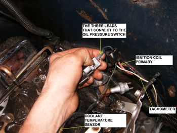
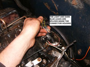
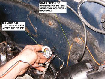
This is a good chance to strip the engine wiring down to the essentials. These are the functions/colors of the wires required to run/monitor/start/charge your engine:
1. The green wire to the coolant temp sender 2. The tan wire to the oil pressure sender (yours is probably shorted to ground) 3. The pink/white power feed to the oil pressure switch 4. The dark blue out of the oil pressure switch to the choke warning light 5. The light blue from the oil pressure switch over to the choke heater 6. The two small wires (red & brown) to the alternator (excitation & voltage indication) 7. The big red to the alternator (battery charging and system supply) 8. The pink to the BATT terminal on the distributor (coil primary feed) 9. The flat braided ground strap (cab firewall to RH cylinder head) 10. The main ground cable from the battery negative to the alternator bracket 11. The white wire to the TACH terminal of the distributor (if you have a tachometer) Note- the following leads are normally grouped together in a single harness connector : 3,4 & 5 - To the oil pressure switch. The blues enter separately and are spliced inside the plug casing. 6 - The small red and brown to the alternator 8 & 11 - Coil primary and pulsed signal for a tachometer Here are some images to help explain:     Other critical wiring in the engine compartment: 1. Main (black) cable from battery positive to the solenoid B terminal 2. The two red branch lines that also go to the B terminal 3. The purple lead from the ignition switch to the solenoid S terminal 4. A tan wire to the brake pressure warning switch on the proportioning valve A nice clear wiring diagram of the 1984 C/K engine compartment: 
|
|
|

|
|
|
#5 |
|
Registered User
Join Date: Sep 2012
Location: CT
Posts: 133
|
Re: Water Temp and Oil Pressure wire identification.
Quote:
What do you mean by shorted to ground? I'm slightly electrically dumb. |
|
|

|
|
|
#6 |
|
Moderator
 Join Date: Oct 2008
Location: Wentworth, NH
Posts: 4,977
|
Re: Water Temp and Oil Pressure wire identification.
If they'll help the GM wiring manuals are in my signature.
The '87 R-V wiring diagrams are a bit of a challenge to wade into till you figure out what the EE intern that drew them was attempting.
__________________
1959 M35A2 LDT465-1D SOLD 1967 Dodge W200 B383, NP420/NP201 SOLD 1969 Dodge Polara 500 B383, A833 SOLD 1972 Ford F250 FE390, NP435/NP205 SOLD 1976 Chevy K20, 6.5L, NV4500/NP208 SOLD 1986 M1008 CUCV SOLD 2000 GMC C2500, TD6.5L, NV4500 2005 Chevy Silverado LS 2500HD 6.0L 4L80E/NP263 2009 Impala SS LS4 V8 RTFM... GM Parts Books, GM Schematics, GM service manuals, and GM training materials...
And please let us know if and how your repairs were successful. |
|
|

|
|
|
#7 |
|
Registered User
Join Date: May 2007
Location: New Hampshire
Posts: 349
|
Re: Water Temp and Oil Pressure wire identification.
What do you mean by shorted to ground?
The sensing leg for the gauge (the tan wire) is connected to the sender. The sender contains a variable resistance to ground (the engine block). The resistance changes according to the oil pressure. The ohm value of that resistance is what positions the needle on the dash gauge. If the insulation on the sensing leg is broken - and the copper wire is touching the truck body - the ohm value of resistance to ground is zero. The gauge reacts as if the oil pressure was sky high. The problem is, I can't remember if the oil pressure gauge will peg high or low if the sensing leg is grounded. But it does't really matter. If you are sure the problem isn't the gauge itself, there is a problem with the sensing leg. If it isn't shorted to ground, the opposite problem exists - the sensing leg is open (i.e. the copper conductor is broken). This results in infinite resistance in the sensing leg. In that case, rather than looking for a section of the tan wire with insulation problems - you will find that the wire is cut somewhere. Take a length of wire, strip the ends and stick one end in the socket that connects to the sender. Touch the other end to a good ground point and observe the gauge. See if it pegs the other way - like if you had zero oil pressure. I think the oil pressure and the coolant temp gauges are wired the same way. So to check which way they peg when the sensing leg has low resistance, do the same test as above with the dark green wire. As I write this, I am starting to think it will peg low. So, I am changing my original diagnosis: If your oil pressure gauge is pegging high when the key is moved to RUN, the sensing leg (tan lead) is broken/cut. The front clip is off my truck so the engine is wide open and easy to work on. I will go out in a bit and ground my oil pressure/coolant sensing legs and find out for sure how each reacts to a dead ground/open circuit. |
|
|

|
|
|
#8 | |
|
Registered User
Join Date: Sep 2012
Location: CT
Posts: 133
|
Re: Water Temp and Oil Pressure wire identification.
Quote:
Please let me know what your results are. |
|
|
|

|
|
|
#9 |
|
Registered User
Join Date: May 2007
Location: New Hampshire
Posts: 349
|
Re: Water Temp and Oil Pressure wire identification.
You did check the fuse labeled GAUGE/IDLE - right?
The only gauges that are protected by that fuse are the oil pressure and coolant temperature gauges. The voltmeter is on a separate circuit and you probably don't use any kind of electric idle control. So if you are not getting any response from your coolant gauge either - check the fuse. Maybe check the fuse first. |
|
|

|
|
|
#10 | |
|
Registered User
Join Date: Sep 2012
Location: CT
Posts: 133
|
Re: Water Temp and Oil Pressure wire identification.
Quote:
I had the truck running for a few days and my voltage guage decided to stop working. Checked the guage/idle fuse and it was blown, after talking to someone experienced with these trucks he told me to replace the 20 amp fuse with a 30 and its been working just fine since. Nothing is tampered with in the harness, are you sure its not on that circuit? |
|
|
|

|
|
|
#11 |
|
Post Whore
 Join Date: Aug 2014
Location: Sacramento, CA
Posts: 10,863
|
Re: Water Temp and Oil Pressure wire identification.
Quote:
|
|
|

|
|
|
#12 |
|
Registered User
Join Date: Apr 2012
Location: san diego ca
Posts: 618
|
Re: Water Temp and Oil Pressure wire identification.
Following
|
|
|

|
|
|
#13 |
|
Registered User
Join Date: Sep 2012
Location: CT
Posts: 133
|
Re: Water Temp and Oil Pressure wire identification.
|
|
|

|
|
|
#14 |
|
Registered User
Join Date: Feb 2015
Location: Fresno
Posts: 34
|
Re: Water Temp and Oil Pressure wire identification.
--PLEASE SEE THE BOTTOM OF THE PAGE LABLED "CORRECTION" BEFORE YOU MAKE ANY ADJUSTMENTS
as pressure/temp rises resistance is decreased. your wire is touching a ground somewhere....but im willing to bet its the circut board. chevy changed a lot each year. I dont have your year Just found my book!!!!, more ground it gets higher the guage....the wire is 5TAN31 and is used on all models in engine compartment...then inside the cab is where it changes depending on model blue wire called 8DK BLU-931 and a note says "inst clstr conn-931 (guages only) " same code, 5tan31 is used to light/NON GUAGE ans is labled "inst luster connector w/o guages" THIS IS WHERE IT GETS TRICKEY.... ------ INSIDE OF CAB: non guage on firewall pass is a tan, and goes to the connector that clips to circutboard n back of cluster the WITH guage model is a DK BLU....... heres that trickey part, the connection points are NOT the same on both models.... with: is connection 931 top of connector 4th position in... without: is connection 31 botton 3rd in. now this being considered, the differences is this: the swaping between the two is: this slot is made into a ground..... what im trying to say is this: if you uses a non guage inst with a guage harnes, instead of that wire going to a guage, it goes to a ground wire specifically, the famous 150black ground splice. so if you swap and intertwine a non guage with guages or guages with non you are going to get what exactally your experiencing. SOLVE: check your harness wire, see if its tan or blue, if its tan, that is a NON guage harness and thats your problem. If its blue, check your circutboard, that bue wire should connect as follows: looking at it head on like your eyes r the socket.....top row, 4th in from the top left, like your reading a book. if your harness shows a black wire there, and a tan wire in the bottom 3rd in, you have a non guage curcutboard. good luck, Reading from a Haynes shop manual 67-87 2wd/4wd 420 edition ____________________________________________________________________________________________________ _____________________________CORRETION: inside the engine compartment a blue 931 is for guages and tan31 is for NON guages. so you have a non guage harness if under the hood is a tan... easy fix, just modify and splice in your cluster connector, remembering to swap correctly..... if you mess up that circut board will....WILL catch on fire, ive done it before on a 71gmc. put the 31 tan in the 150 black's spot, and the black in tans spot and back to 150 black ground, aka, swap the tan and black wire...... i believe.... get a book hahaha its hard to explain and i dont have pictures, maybe someone can help u wih that Last edited by reporter000001; 02-18-2015 at 12:56 AM. Reason: woah |
|
|

|
|
|
#15 |
|
Registered User
Join Date: Feb 2015
Location: Fresno
Posts: 34
|
Re: Water Temp and Oil Pressure wire identification.
here:
i retyped it.. ok ive edited this so many times, i found my book, as heat increases resistance goes down, thus that wire is touching a direct ground. book showed me this: if under ur hood is a tan wire, you have a NON guage harnes. if you have a blue wire you have a guage harness. chevy switched the plug for the cluster guages with non guages and guages, aka lights or guages. on the plug for the cluster, looking at it straight on, the top row, 4th in is a blue for guages. for non guages aka warning lights that wire is a black.... aka ground. solution: take your tan wire you have and put it in the black spot, take the black and put it in the tans spot. or just get matching stuff, junkyards r cheap..... if this changed, so did many other things, this is a fire waiting to start i highly suggest you find a new circutboard or wireing harness... |
|
|

|
 |
| Bookmarks |
|
|