
|
 03-02-2016, 06:37 PM
|
#1 |
|
Registered User
Join Date: Sep 2012
Location: oceanside CA
Posts: 706
|
charging system
hey guys i was wondering what is the highest Amp Alternator i can run in my truck with out having to rewire the entire truck ?
|

|

|
|
03-02-2016, 07:41 PM
|
#2 |
|
Registered User
Join Date: Jan 2013
Location: Calgary Alberta
Posts: 1,170
|
Re: charging system
As far as I know any size you want as long as the wires from alternator back to battery are increased to an appropriate size. #8 is probably good for a 100A alternator. That's what I did with a fusible link at the battery. Some of the pros on here will probably give you a more detailed explanation.
|
|
|
|
|
03-02-2016, 08:12 PM
|
#3 |
|
Senior Member
 Join Date: Jan 2011
Location: Hayes Va
Posts: 4,569
|
Re: charging system
If you are going to a one wire alternator you run the charge wire to the alternator and run at least a #8 over to the horn relay. That will get you running. Now the wiring harness in the truck still runs through the amp meter. So you see a discharge when stuff is on. I would jump out the amp meter as they tend to burn up if you over load them. The entire rest of the harness is limited based on its design. So even though you have lots of power in the alternator you cant use it unless you pull from the battery.
Jimmy
__________________
60 to 66 Chevy and GMC window decals http://67-72chevytrucks.com/vboard/s...d.php?t=661131 Good friends, good food and a hotrod what else do you need? 1966 BBW long fleet Daily driver 1965 BBW short fleet Sold and going to a good home 1965 Suburban 2003 3500 Duramax 2005 Ultra Classic |
|
|
|
|
03-02-2016, 08:16 PM
|
#4 |
|
Registered User
Join Date: Nov 2009
Location: Sherman, ME
Posts: 2,366
|
Re: charging system
60-62 originally used generators so those years will need some wiring changes to use any alternator.
63-66 originally had the output of the alternator routed through a 12ga wire to a junction block that's part of the horn relay. That section needs to be replaced with heavier wire to handle a higher output alternator. Another 12ga wire ran from the junction on the horn relay over to the positive battery post. This section of wire carries current to the battery to keep it charged. And it supplies power from the battery to the truck's electrical system when the engine is not running. Depending on the loads you'll be running with the engine off, you might need to upgrade this wire as well. This wire also serves as the "shunt" for the stock ammeter (if your truck is equipped with stock gauges). Upgrading this wire will allow the ammeter to safely handle higher currents but will decrease it's sensitivity. And if you do have an ammeter, I'd recommend adding a couple of 4A inline fuses to the lead-in wires like GM did in the 67+ trucks. Also, adding a fusible link to the battery end of this wire is definitely a good idea. A 3rd 12ga wire runs from the junction on the horn relay to inside the cab to power the fuse box, ignition switch, headlight switch, etc. This wire should be adequate for the stock loads inside the truck. If you add any additional loads that will take advantage of the higher output alternator, connect them directly to the junction on the horn relay. And if necessary, upgrade that to a heavier duty junction block. Connecting the added loads here will avoid overloading that 12ga wire that feeds power into the cab. And use fusible links, fuses, or circuit breakers to protect the wiring feeding the added loads. |
|
|
|
|
03-02-2016, 08:40 PM
|
#5 | |
|
Registered User
Join Date: Sep 2012
Location: oceanside CA
Posts: 706
|
Re: charging system
Quote:
 the PO ripped all that out it dose have a GM 1 Wire in it but i was looking for maybe putting in a higher amp one to get much better charging from it . right now if you turn on the blinker the volt needle on my After Market charge gauge jumps with each tick .... also with the fan on and lights at night its charging at like 10 .. no horn relay because the PO put in a separate button and a cheap electric air horn lol ... so is there any other ideas on how to run the wire with out a horn relay ? the PO ripped all that out it dose have a GM 1 Wire in it but i was looking for maybe putting in a higher amp one to get much better charging from it . right now if you turn on the blinker the volt needle on my After Market charge gauge jumps with each tick .... also with the fan on and lights at night its charging at like 10 .. no horn relay because the PO put in a separate button and a cheap electric air horn lol ... so is there any other ideas on how to run the wire with out a horn relay ?
|
|
|
|
|
|
03-02-2016, 08:57 PM
|
#6 | |
|
Registered User
Join Date: Nov 2009
Location: Sherman, ME
Posts: 2,366
|
Re: charging system
Quote:
As far as the alternator upgrade goes, it sounds like you might have some other electrical issues (such as poor high-resistance connections) that are creating voltage drops in your system. A new alternator might not be the cure. And how did the previous owner re-connect the charging system wiring after they ripped out the stock horn relay? The connections they made could be part of the problem. You can use something like one of these to take the place of the junction that was built into the stock horn relay: 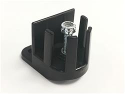 or  or other similar junctions. |
|
|
|
|
|
03-02-2016, 09:10 PM
|
#7 | |
|
Registered User
Join Date: Sep 2012
Location: oceanside CA
Posts: 706
|
Re: charging system
Quote:
|
|
|
|
|
|
03-02-2016, 09:25 PM
|
#8 |
|
Registered User
Join Date: Jun 2013
Location: Somewhere
Posts: 3,123
|
Re: charging system
The x Amp output of an alternator is is the max draw it supports. Amps are drawn/pulled by the load, not pushed by the source.
Volts measure force/pressure and a later alt may put out a higher voltage (check the voltmeter on your late model whatever). That higher voltage may increase current through the existing system, but the amp rating of the alt has nothing to do with it. A crappy electrical system (wiring) will make bad (resistive) connections more noticeable when they create more heat, which may cause smoke. Bottom line. Bad wiring is bad, but the alternator amp output is what the load needs, not the rated number. Google Ohm's Law to get the relationships between voltage, current and resistance. Its very understandable. |
|
|
|
|
03-02-2016, 09:29 PM
|
#9 | ||
|
Registered User
Join Date: Nov 2009
Location: Sherman, ME
Posts: 2,366
|
Re: charging system
Quote:
Quote:
Then hook a voltmeter to some convenient test points on either side of the connection in question and place a load on the system (by turning on the lights, heater, etc). If the connection is good, there should be a minimal voltage drop across it. |
||
|
|
|
|
03-02-2016, 09:56 PM
|
#10 | |
|
Registered User
Join Date: Sep 2012
Location: oceanside CA
Posts: 706
|
Re: charging system
Quote:
|
|
|
|
|
|
03-02-2016, 10:15 PM
|
#11 |
|
Registered User
Join Date: Sep 2012
Location: oceanside CA
Posts: 706
|
Re: charging system
Here are some pics of what I have going on I hope they help you to help me thanks for your patience
|
|
|
|
|
03-02-2016, 10:49 PM
|
#12 |
|
Registered User
Join Date: Jun 2013
Location: Somewhere
Posts: 3,123
|
Re: charging system
I guess an understanding is unneeded. Pics are the point. They carry the truth.
Electricity works as as majority or the mob rules. Keep talking. |
|
|
|
|
03-02-2016, 10:52 PM
|
#13 | |
|
Registered User
Join Date: Sep 2012
Location: oceanside CA
Posts: 706
|
Re: charging system
Quote:
|
|
|
|
|
|
03-02-2016, 11:02 PM
|
#14 |
|
Registered User
Join Date: Jan 2013
Location: Calgary Alberta
Posts: 1,170
|
Re: charging system
It looks like your alternator is a 12 si. The brown wire connected to the #2 goes to the light. The white from #1 usually goes to a key on source although hard to tell in the picture where it goes. The red alternator output wire looks like maybe it is only 12 ga. Follow that back to the battery for good connections and maybe replace it to a larger gauge.
|
|
|
|
|
03-02-2016, 11:11 PM
|
#15 | |
|
Registered User
Join Date: Sep 2012
Location: oceanside CA
Posts: 706
|
Re: charging system
Quote:
|
|
|
|
|
|
03-02-2016, 11:16 PM
|
#16 |
|
Registered User
Join Date: Jan 2013
Location: Calgary Alberta
Posts: 1,170
|
Re: charging system
I made a mistake on my above post. #2 usually goes to where you want to sense the voltage or in its most simple way connect it to the alternator output post. #1 is the one that goes to the light or ignition source but the experts can explain in better detail what is required with it..
|
|
|
|
|
03-02-2016, 11:30 PM
|
#17 |
|
Registered User
Join Date: Jan 2013
Location: Calgary Alberta
Posts: 1,170
|
Re: charging system
I think #1 usually supplies the ground for the light when the key is turned on. After the alternator starts charging the ground is removed and the light goes out. If there is no light maybe they hook #1 to an ignition source to get the alternator to excite and start charging. Some of them want a little resistance but I don't know about the 12 si. Look online for 10si and 12 si wiring diagrams. Like the others have said I think some of your connections may be loose.
|
|
|
|
|
03-02-2016, 11:38 PM
|
#18 | |
|
Registered User
Join Date: Nov 2009
Location: Sherman, ME
Posts: 2,366
|
Re: charging system
Quote:
In a nut shell, the stock system had 3 hot wires connected together at the horn relay junction, (1) the alternator output wire, (2) the wire going to the battery, and (3) the main feed wire into the cab. I was simply stating that you could tie those 3 wires together using one of the junction blocks I pictured instead of the stock horn relay. As an alternative to using the junction block, you could simply run the output of the alternator to the positive battery terminal. And hook the main feed going into the cab to the positive battery terminal as well. I have a feeling this is how yours is configured now. It will work but doesn't have some of the advantages of the factory system. Also, that white wire that's not connected to anything on your alternator should be hooked up as vince1 just described. And yes, the SI-series alternators need about 10Ω in the circuit if you're not hooking it up to a light. That wire provides power to excite the field and start charging. Without it the alternator won't charge. Although some regulators (such as a "1-wire" regulator) will "self excite" once the alternator reaches a certain speed. |
|
|
|
|
|
03-03-2016, 12:06 AM
|
#19 |
|
Registered User
Join Date: Jan 2013
Location: Calgary Alberta
Posts: 1,170
|
Re: charging system
What voltage are you getting across the battery posts with it running? Should be around 14 to 14.5.
|
|
|
|
|
03-03-2016, 01:12 AM
|
#20 |
|
Registered User
Join Date: Sep 2012
Location: oceanside CA
Posts: 706
|
Re: charging system
ok so then should i take that white wire and ad to it and run it inside the cab to my key switch then ? right now if you start the truck it wont charge till you give it a quick rev then the needle jumps to a charge
|
|
|
|
|
03-03-2016, 02:07 AM
|
#21 | |
|
Registered User
Join Date: Sep 2012
Location: oceanside CA
Posts: 706
|
Re: charging system
Quote:
then i turned on a blinker and re tested and with each tick of the flasher it would show 14.38 and then tick 14.37 then back to 14.38 same over and over ..... now then i let it get warm so the fan would kick on and with that on and the headlights it was a steady 14.30 i hope this is the info you were wanting thanks to all of you helping me with this |
|
|
|
|
|
03-03-2016, 08:03 AM
|
#22 |
|
Senior Member
Join Date: Jan 2011
Location: Hayes Va
Posts: 4,569
|
Re: charging system
That shows the alternator is working like it should. Now it looks like you need to start cleaning up the wiring in the truck. First thing I would do is rewire the truck but that is not always an option. Start by getting rid of butt splices and replacing them with solder joints and shrink wrap. Next Look at the wire from the charge on the alternator to the battery I would run a new one in 8 gauge wire. Then try and trace the wire from the battery to the fuse block. This wire is important for powering the truck. I would get a junction block and put it where the horn relay used to be. Run a #8 wire from it to the battery. Take the wire that powers the fuse block and run it to it. Now that should help. Next thing is to find the wire powering the fan relay an run it to the junction block. Next is a good ground. Make sure the ground from the battery tot he engine is solid. Next run a number #8 ground wire from the battery to the core support. Next make sure you have a ground wire from the cab to the engine. I like to run two. Now run a ground from the engine to the frame. I use smaller battery cable from the parts store. Now make up a ground wire for the hood to the cab. The last ground I install is from the cross sill on the bed to the frame. All these grounds work wonders at getting lighting issues to go away. I even have ground wires from my tail light housings to the bed. This will get you started and you will have solid power and ground. Then you will be better able to sort out the rest of the PO's mess.
Jimmy
__________________
60 to 66 Chevy and GMC window decals http://67-72chevytrucks.com/vboard/s...d.php?t=661131 Good friends, good food and a hotrod what else do you need? 1966 BBW long fleet Daily driver 1965 BBW short fleet Sold and going to a good home 1965 Suburban 2003 3500 Duramax 2005 Ultra Classic |
|
|
|
|
03-03-2016, 10:49 AM
|
#23 |
|
Registered User
Join Date: Jan 2013
Location: Calgary Alberta
Posts: 1,170
|
Re: charging system
Yeah running the #1 to the ignition source will start it charging right away but you should have the resistor in line with it to take the place of the non-existent bulb. Maybe others can advise as to P/n's watts, ohms or whatever. Good advice about adding more grounds and such. Some people here go way beyond my knowledge and usual just get it working skills.
|
|
|
|
|
03-03-2016, 03:33 PM
|
#24 |
|
Registered User
Join Date: Sep 2012
Location: oceanside CA
Posts: 706
|
Re: charging system
Hey thanks guys for all your patience with me . And helping me with all this valuable information. All of you were a big help to me it's refreshing to get that and not my usual insults and mean comments. I can't learn if I never ask but most times because I do ask for extra help in understanding things . I get hateful comments instead I don't have much tools and such yet but I don't want to be the guy who always pays others to fix his truck up . I feel that if given enough time by others I can learn how to do it ... and that is what you guys did for me so from the bottom of my heart Thank You
 Happy Truckin Happy Truckin
|
|
|
|
|
03-04-2016, 07:51 AM
|
#25 |
|
Senior Member
Join Date: Jan 2011
Location: Hayes Va
Posts: 4,569
|
Re: charging system
Flea markets and pawn shops for tools and time for learning. You will get there with your truck. What makes things harder on a lot of these trucks is what previous owners have done. You just want to poke them in the eye with a sharp stick. Not knowing the sins of the past on the truck makes it real hard at times to give or get good solutions to problems.
Jimmy
__________________
60 to 66 Chevy and GMC window decals http://67-72chevytrucks.com/vboard/s...d.php?t=661131 Good friends, good food and a hotrod what else do you need? 1966 BBW long fleet Daily driver 1965 BBW short fleet Sold and going to a good home 1965 Suburban 2003 3500 Duramax 2005 Ultra Classic |
|
|
|
 |
| Bookmarks |
|
|


 Linear Mode

