
|
Register or Log In To remove these advertisements. |
|
|
|
|||||||
 |
|
|
Thread Tools | Display Modes |
 06-20-2023, 05:24 PM
|
#26 |
|
Registered User
 Join Date: Jul 2007
Location: Toppenish, WA
Posts: 16,395
|
Re: Battery draining
I really don't want to get too distracted or off base in this thread.
Testing the battery you really do have to have it fully charged and then use test equipment that Dsracven mentioned in post 24 that actually puts the proper load on the battery for the correct amount of time and shows the results. I don't know brand or model but the local Les Schwab tire store (big chain in the Pacific Northwest ) has but it is one of the best and most complete testers I have seen. You need equipment like that to test it right and it will test the charging system along with the battery. Back to Phungki's truck, from reading what it has and doesn't have there isn't much there to cause a parasitic drain. None of the usual stuff that drains a battery after a period of time if you don't have a battery tender on it. The anti theft system in my BMW draws a tiny bit of power all the time even if you don't have the alarm turned on. It's not a bother if you drive it on a regular basis but drains the battery if it sits for a month. Things like an alarm system, clock in the radio, an amp that isn't shut off by the ignition switch. light in the glove box that doesn't go off when you close the door, trunk light that doesn't go off when you close the trunk. I had a student who owned a nice 64 Chevy lowrider that he had a lot of work and money in and left at home when he went to work beause the parking lot where he worked was famous for door dings by careless people. Every morning the battery was dead and he would have to jump it to start it to get to school. we tested battery, alternator and everything else and no issues. We even had the sun scope hooked to it to check the alternator on the scope. After a couple of weeks of battling it he was fussing about it to his mom and she goes "oh, your brother and his friends have been listiening to your car sterio while you are at work at nights." Little bro found out real quick that that was not to happen again and no problem from then on out. Billy's dirty battery in his mid 60's Chevy truck was the other one. That was the first time I had seen that and I have seen it several times since.
__________________
Founding member of the too many projects, too little time and money club. My ongoing truck projects: 48 Chev 3100 that will run a 292 Six. 71 GMC 2500 that is getting a Cad 500 transplant. 77 C 30 dualie, 454, 4 speed with a 10 foot flatbed and hoist. It does the heavy work and hauls the projects around. |

|

|
|
06-22-2023, 08:58 PM
|
#27 |
|
Registered User
Join Date: Sep 2018
Location: Blissfield MI
Posts: 255
|
Re: Battery draining
So I was able to get back out there tonight. I have a -13.08 parasitic draw.
Started with the alternator. Disconnected the main wire, alternator to battery. nothing changed. Reconnected wire. I disconnected the white (exciter) and the red (battery) wires and the draw went to -4.36. left them disconnected and disconnected the main wire again and the draw went to -0.07. If I connect either the white or red wire again by itself the draw goes back to -13 again. I do not have a diode on the white exciter wire. possibly the issue? from what I've read its supposed to allow the vehicle to be shut off, right? Something about stopping the current from traveling back. It does shut off normally. ya'll have been great btw. I spend half my time frustrated and the other half happier than i pig in ....well you know. Is this normal? |
|
|
|
|
06-23-2023, 12:36 AM
|
#28 |
|
Registered User
Join Date: Nov 2010
Location: calgary alberta
Posts: 9,041
|
Re: Battery draining
sounds like you figured it out. it's what I personally thought it was gonna be after you said there was basically nothing else connected except stuff to make it run. otherwise I figured a stuck relay that won't turn off. again, a pic would be great just so we can see the style of alternator you are workng with. do you have another spare one you could lay next to the other one and simply do the wiring on it without mounting it? use a jumper wire to ground the housing. would be worth doing just to see if it is your wiring or the alternator that is giving you an issue.
this link explains it pretty well. basically the one connector in the rectangular push in plug (the one closest to the battery cable connection charge wire) is not really needed unless you want a "no charge indicator" light on the dash.kinda a good idea I think but thats just me. this works by feeding keyed battery power to the light on the dash. the other side of that light connection that usually would go to ground actually goes to that terminal on the alsternator and uses that connection as a ground when the alternator isn't charging. that makes the bulb light up according to the amount of ground the alternator is giving. this may be dim or maybe even pulsating when the engine is first started and hasn't been revved up yet to get the alternator to charge. when the alternator has been revved up some it will start charging and feed power down the ine that is connected to the charge indicator bulb. this effectively gives the bulb power on both sides of the bulb filament so it will go out because it just lost it's ground circuit. the other terminal on the plug in connection, the one that goes to the ignition switch and is powered with the key on, is the one that will "excite" the alternator and make it charge. a lot of guys wire that directly to the battery charge connection on the alternator. some of these alternators have a third terminal in the plug whicch is for running a tachometer. not too many of those out there so you don't likely need to worry about that. https://smithcoelectric.com/blogs/te...wiring-diagram and here is another link that explains it further in depth than what I could muster up from memory. haha https://vintageautogarage.com/p10si-...ug-with-diode/ |
|
|
|
|
06-23-2023, 01:12 AM
|
#29 |
|
Registered User
Join Date: Mar 2022
Location: Surrey BC
Posts: 1,398
|
Re: Battery draining
The numbers you give are volts right?
The exciter wire drawing power when the key was off is clearly a problem. But the fact that you still had a current leak of 4 volts when the alternator was fully disconnected says to me the alternator is either not the problem or not the only problem. Getting only 4 volts indicates a high resistance somewhere. I'm wondering about your ignition switch, is it new or used? OEM style in dash or attached to the steering column? How many connectors on it? If you unplug it does the rest of the current leak stop? There is a possibility the new wire harness has issues, but it sounds like you were careful with it and assuming a factory flaw on a name brand kit maybe a stretch |
|
|
|
|
06-23-2023, 01:32 AM
|
#30 |
|
Registered User
Join Date: Nov 2010
Location: calgary alberta
Posts: 9,041
|
Re: Battery draining
Yes, and that was why I asked sorta the same questions. What alternator and what sort of ignition switch scenario.
Again, a pic says a thousand words. Disconnect the alternator completely and look for any other draws with key off. Actually, with alt disconnected try what LG says and also disconnect your ignition switch plug in or, if dash mounted old fashioned key switch, pull the power wire off that and see if your draw goes away. Are you running any relays? Have you checked them to ensure they turn off with key off? Do you have a fuse panel and if so have you checked the fuses to see if they are all non powered with the ignition off? |
|
|
|
|
06-23-2023, 06:44 AM
|
#31 | |
|
Registered User
Join Date: Sep 2018
Location: Blissfield MI
Posts: 255
|
Re: Battery draining
Quote:
It is a new ignition switch, oem style in the dash from LMC. I will look further into the ignition switch next |
|
|
|
|
|
06-23-2023, 06:53 AM
|
#32 | |
|
Registered User
Join Date: Sep 2018
Location: Blissfield MI
Posts: 255
|
Re: Battery draining
Quote:
I dont know how to check to see if the fuses are powered down with the key off. Ill need to look into that. I believe there is a wire that goes between the battery and the fuse box directly. Wouldnt that mean there would be some power to the fuse box all the time? A small amount at least |
|
|
|
|
|
06-23-2023, 09:58 AM
|
#33 |
|
Registered User
Join Date: Mar 2022
Location: Surrey BC
Posts: 1,398
|
Re: Battery draining
>draws 4v when the plugs containing the 2 small wires is removed but the wire going between the alternator and battery is still connected.
This sounds like alternator problem. does it go to zero when all the wires are disconnected from alternator? Yes -> leave alternator fully disconnected and use some other piece of wire to bridge from battery to the main terminal on alternator, if you still get 4v I think the problem causing the low voltage leak is inside alternator, if the problem goes away there is a short in that main cable to ground. No -> there is another leak somewhere with high resistance, unplug more stuff until you see the voltage go to zero - start with ignition switch The larger leak when either red or white wire is connected: the white exciter wire problem is either the ignition switch or you do need to add a diode to stop back feed of power from alternator to ignition. Does wiring kit instructions say anything about diodes? White wire basically turns the alternator on with ingition. The red wire, where does the other end go to? Red wire should be live only when ignition is on, its purpose is to let the alternator see the voltage of the system from somewhere away from the battery to adjust for any voltage drop due to the loads. Usually goes to somewhere near fuse box. without it, the alternator may overcharge, if it connects too close to the battery and there is voltage drop in the system some parts of the truck may be getting too few volts. Fuse box will always have some power: horn lights and brakes at least will always have power. other fuses will only be hot when the ignition is on. a test light like this is my goto for finding out what has voltage and what does not. get them anywhere for a few bucks Also very handy is a few wires with jumper connectors on each ends so you can hook stuff up temporarily to see if it works. I made up a pair of truck length jumper wires from some old speaker wire, it has been very useful for testing on several car and boat projects we have going on. ps: I edited the yes/no paragraph a couple hours after the original post as what I wrote earlier did not look right after a cup of coffee. Last edited by leegreen; 06-23-2023 at 12:26 PM. |
|
|
|
|
06-23-2023, 10:54 AM
|
#34 |
|
Registered User
Join Date: Nov 2010
Location: calgary alberta
Posts: 9,041
|
Re: Battery draining
LG is on the same diagnosing thought process as me on this. It's why I said to totally disconnect the alternator and see if the problem goes away. New alternators can be faulty too, maybe a bad part or maybe dropped somewhere along the supply chain. Who knows.
A test light is a must have and are only a few bucks. Some have an audible alarm as well as a light. Try to get one that has a decent clamp on the end so it grips well and will stay put. Test wires, or jumper wires can be made up cheap as well or you can buy a cheap set too. Try to find some with good alligator clips on the ends with color coded flexible insulators over the clips as sometimes you need to test a circuit that is right next to another circuit or ground. Also try for flexible wire as regular car wire can be kinda stiff sometimes and will pull the clip off. If you need to check power from a connector with small connectors and the test light light is kinda big to fit I use a small pin with a little circle bent into one end and then flattened to form a T. You can get them cheap from an office supply or a craft store or online. They are called t pins. Used for cork boards, fabric etc. |
|
|
|
|
06-23-2023, 11:21 AM
|
#35 |
|
Registered User
Join Date: Nov 2010
Location: calgary alberta
Posts: 9,041
|
Re: Battery draining
t pins
https://www.thefibrenook.com/products/t-pins alternator charge plug https://www.wiringdepot.com/store/c/...s-Sockets.aspx circuit tester https://www.harborfreight.com/612v-c...ead-63603.html test leads https://www.harborfreight.com/18-inc...ads-66717.html https://www.harborfreight.com/36-inc...ads-66712.html clips only to make your own leads https://www.harborfreight.com/28-pie...set-67589.html not saying any of these items are any good, just some pics to show what to look for. to test the fuse panel for what circuits are hot with key off simply connect the test light clip to a good ground, test it on a circuit that is hot so you know the ground is good, then touch the pointed tip to the fuse and see if it lights up the tester. without knowing what type of fuses you have I would assume you have the newer style push in plastic fuses, like an ATO or ATC fuse. these have 2 little tabs that protrude a little through the plastic on the outboard side of the fuse, you can see them when the fuse is installed. these are extensions of the blades that actually plug into the circuit. you can touch these with your tester to see if the fuse is powered or not. if you have power on one side but not the other then the fuse is getting power but it is also blown, thats why it's only powered on one side. this makes it easy to test for power without pulling the fuse out for each circuit. if you have the old fashioned glass fuses simply touch the one end of the barrel of the fuse where the metal part is. its good to test both ends of any fuse just to ensure it isn't blown. do you have a fuse or breaker on the power wire that feeds the fuse panel? something close to the battery maybe? otherwise that run of wire is vulnerable to a short. sometimes one of these fuses will look like this link, called a mega fuse https://www.summitracing.com/parts/a...BoC6AUQAvD_BwE |
|
|
|
|
06-24-2023, 07:42 PM
|
#36 | |
|
Registered User
Join Date: Sep 2018
Location: Blissfield MI
Posts: 255
|
Re: Battery draining
Quote:
|
|
|
|
|
|
06-24-2023, 07:58 PM
|
#37 | |
|
Registered User
Join Date: Sep 2018
Location: Blissfield MI
Posts: 255
|
Re: Battery draining
Quote:
Yes I get a parasitic draw of .07 when all 3 wires are removed. I need to dig into the ignition switch again when I get back out there. I found the diode in my wiring kit, pretty sure I need to put that in. Might not solve the problem but Im going to do that before taking the alternator back and having it tested. Yes Ive bought brand new/refurbished parts before and had them not work or cause a fuse to blow. Jeep TJ wiper motor comes to mind. Tried twice then just bought a used one on ebay. I actually already have T pins. As soon as I can wrap my head around how you want me to use them Ill dig them out 😁 Thank you all for the help |
|
|
|
|
|
06-24-2023, 09:27 PM
|
#38 |
|
Registered User
Join Date: Sep 2018
Location: Blissfield MI
Posts: 255
|
Re: Battery draining
I put in the diode. Nothing changed. I looked over the ignition switch. Everything seems to where its supposed to be. I pulled every wire one at a time. I would get little movements on the multimeter but was still a 13v draw. Pulled all the fuse one at a time. Same results as the ignition switch. I guess now Ill take the alternator in and have it checked. Ill grab a test light while Im there
|
|
|
|
|
06-25-2023, 12:36 AM
|
#39 |
|
Registered User
Join Date: Mar 2022
Location: Surrey BC
Posts: 1,398
|
Re: Battery draining
Confirm you can make it go to zero - pull the main battery + connection ?
With the ignition switch unplugged you still got full voltage on the 2 alternator wires? Your fuse panel probably has a relay for horn and flasher for hazard - they will always have power, did you try pulling them? what painless kit # is it? |
|
|
|
|
06-25-2023, 02:16 AM
|
#40 |
|
Registered User
Join Date: Nov 2010
Location: calgary alberta
Posts: 9,041
|
Re: Battery draining
the T pins work for pushing into a connector on the back side where the wire comes out so you can get a reading on voltage etc as the friction between the pin, the connector housing and the terminal inside the housing is enough to keep the pin in place and also give a reading thats pretty accurate. this is without poking a hole through the wire insulation on the wire so no mechanical damage is done. some guys do that poking thing all the time with the sharp end off the test light and think nothing of it. it drives me crazy because somebody like me, who works in a shop (used to), would have to find the spot in that circuit that is causing the resistance problem and then fix the spot by cutting the bad corroded spot out and repairing it. if you do that poky thing because you have no choice ensure you seal the hole you poked with some liquid electrical tape or something more than regular electrical tape. if you do use regular electrical tape use the bright red stuff so that spot sticks out like a sore thumb and the repair guy after you can easily find it.
end of rant. T pins work good for that. I also have used a strand of wire pulled from a spare length and wrapped around the terminal in question when the connector is unplugged. then plug the connection together and that short strand of wire sticks out enough to connect a tester or aligator clip to. another thing i will mention is that while the digital multimeter is great but for doing tests to find parasitic draws sometimes an analog multimeter is easier to use because the digital readout ones are always hunting for the number. the analog ones simply move the needle a little or a lot and o can give sort of an average number that is close enough for testing like this until you get right down to the short hairs. what I have also done in the past is use an incandescent trailer light with an alligator clip on each of the pigtail wires . the kind of light that is a sealed beam. disconnect the negative battery post and install the trailer light in the circuit between the cable and the battery terminal. you can do the same thing with your test light but you gotta hold it there or clamp it to the battery post somehow. a large draw will light the bulb brightly, less draw will light it dimly. you are looking for no light at all. simply do one change at a time and look at the bulb from where you are working. it is easy to see if the bulb is lit brightly, dimly or not lit. when not lit it may be because there isn't enough draw to light the bulb. that is when you start using the analog multimeter. it can also be set up so you can see it from where you are working if you have a large enough gauge. some surplus stores have panel meters which are larger and possibly cheap too. I have also done that trick using a buzzer from a car instead of the trailer light. for those times when you are looking for a draw in a spot where it is awkward to see the light or meter or whatever. if the buzzer is buzzing then there is still a draw enough to make the buzzer operate. |
|
|
|
|
06-25-2023, 02:23 AM
|
#41 | |
|
Registered User
Join Date: Nov 2010
Location: calgary alberta
Posts: 9,041
|
Re: Battery draining
Quote:
when you pulled every wire one at a time did you leave them disconnected and move to the next wire? the alt can have one wire directly wired to the positive charge connection and shouldn't back feed. the other wire should only be powered with key in the run position. thats why some guys wire that to the ignition coil wire (if they don't have a ballast resistor) because the coil only gets power with the key in run (or start) |
|
|
|
|
|
06-25-2023, 08:05 AM
|
#42 | |
|
Registered User
Join Date: Sep 2018
Location: Blissfield MI
Posts: 255
|
Re: Battery draining
Quote:
I only pulled one wire at a time in the ignition. Connecting it back once it made no change. I did not pull the relays in the fuse box tho. Last edited by Rickysnickers; 06-25-2023 at 09:52 AM. |
|
|
|
|
|
06-25-2023, 08:09 AM
|
#43 | |
|
Registered User
Join Date: Sep 2018
Location: Blissfield MI
Posts: 255
|
Re: Battery draining
Quote:
No I plugged each one back in after it had no effect. Since you and LG asked me that maybe I need to unplug them all? |
|
|
|
|
|
06-25-2023, 08:57 AM
|
#44 |
|
Registered User
Join Date: Mar 2022
Location: Surrey BC
Posts: 1,398
|
Re: Battery draining
I should have explained more: pull the main battery positive cable off to confirm the multimer does go to zero: I want to confirm the MM does go to zero and that there is no other power source, a capacitor for instance we are chasing.
If the Ign switch is faulty with internal short between multiple wires you may need to disconnect all the wires at once. |
|
|
|
|
06-25-2023, 09:28 AM
|
#45 |
|
Registered User
Join Date: Mar 2022
Location: Surrey BC
Posts: 1,398
|
Re: Battery draining
here is the manual for that harness
https://www.painlessperformance.com/Manuals/20105.pdf and the battery/charge section So the red wire to alt will always be hot, but when the alternator is not running connecting it should not result in a current draw so test your alternator The white wire should not be hot when the switch is off. Put MM or test light between white wire and ground. 1) unplug everything on the ign switch, if it is still hot pull the midi fuse between battery and fuse block, it should go dead. If it does not maybe there is a short between two positive wires between fuse box and battery. 2)If the voltage goes to zero with midi fuse pulled put it back, lets look at fuse panel: The hazard flasher, horn relay and all the fuses in lower diagram (constant power) should be pulled one by one until the voltage goes away or you have them all pulled. If you still have voltage on white wire start pulling everything else on the fuse panel until it is empty. If you still have voltage with empty fuse panel there is a short in the panel or the main wiring harness. and maybe it is time to call painless Hope this helps Last edited by Rickysnickers; 06-25-2023 at 09:56 AM. |
|
|
|
|
06-25-2023, 09:32 AM
|
#46 |
|
Registered User
Join Date: Mar 2022
Location: Surrey BC
Posts: 1,398
|
Re: Battery draining
I'm not sure why the charge diagram is showing up twice in my last post, I can't fix it
|
|
|
|
|
06-25-2023, 09:56 AM
|
#47 |
|
Senior Member
 Join Date: Oct 2014
Location: Eagle, ID
Posts: 3,406
|
Re: Battery draining
I think I fixed it.
|
|
|
|
|
06-25-2023, 10:38 AM
|
#48 |
|
Registered User
Join Date: Nov 2010
Location: calgary alberta
Posts: 9,041
|
Re: Battery draining
great to hear. don't worry about telling us what the problem was....we are fine just knowing you got it.....
just kidding, now fess up.haha |
|
|
|
|
06-25-2023, 10:40 AM
|
#49 |
|
Registered User
Join Date: Nov 2010
Location: calgary alberta
Posts: 9,041
|
Re: Battery draining
sorry, I misread that the post was from rickysnickers and not phungki. lol. please disregard my post 48.
|
|
|
|
|
06-25-2023, 12:42 PM
|
#50 | |
|
Registered User
Join Date: Jul 2007
Location: Toppenish, WA
Posts: 16,395
|
Re: Battery draining
Quote:
Normally people either use the idiot light for the alternator or that diode to prevent the feedback. That is the fix for "I just put and alternator on my truck and drove it and it charged great but now the engine won't shut off when I turn the key off. There should be no power though that wire with the key off. None=0 There should be no power at the pin for the exciter wire on the alternator with the key off. This is how many of us who aren't putting in a complete wiring kit install an internal regulator Delco alternator 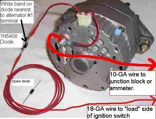 The white band on the diode shows which way the power flow goes. There are two sets of diodes inside the alternator. The diode trio and the diode bridge. One or the other of those is what usually goes bad. They can be tested by taking the alternator apart but most parts houses don't keep them in stock. 25 years ago I was told by the counterman in a NAPA store that I was the only person in the area still rebuilding his own alternators. It isn't that common for an individual to do that anymore even though for someone with training and experience the degree of difficulty isn't that hard. These diodes are again one way check valves for electricity The tri diode  And or the diode bridge or Rectifier.  Those two from Summit cost almost as much as a lifetime guareentee alternator from O'Reilly's" That is why folks normally don't rebuild an alternator at home unless it is an "original" to the car or truck unit with the correct numbers that it left the factory and you are doing a 100 point restoration. Or you are cheap like me and hunt down the discount price parts and rebuild your own. I really don't want you to take it apart because then I will have to write out a lengthy set of instructions and have to go take one apart to add photos to those instructions. I can do it and may do it as a separate tech thread some day.
__________________
Founding member of the too many projects, too little time and money club. My ongoing truck projects: 48 Chev 3100 that will run a 292 Six. 71 GMC 2500 that is getting a Cad 500 transplant. 77 C 30 dualie, 454, 4 speed with a 10 foot flatbed and hoist. It does the heavy work and hauls the projects around. |
|
|
|
|
|
| Bookmarks |
|
|


 Linear Mode

